4 • Basic Application Configurations | Model 3086 G.SHDSL Integrated Access Device User Guide |
|
|
installed at a Central Office should be set to CO. For
Setting | |
|
|
Off | CP |
ON | CO |
|
|
Switch
| Clock mode |
|
|
Off | Internal. Transmit Clock to DTE is generated internally by the Model 3086 |
On | External. Transmist Clock to DTE is generated from external clock signal received |
| from DTE. (This option is only available when the Model 3086 is set to CO mode. |
|
|
T1 Interface
The 3086 enables T1 or E1 device located at customer locations to access a carrier’s network over two wire, long reach DSL links. This capability allows providers to offer T1/E1 services at customer locations that were previously outside the reach of standard T1/E1 lines.
The 3086/K offers a user configurable T1 or E1 interface. Selection of the interface is done via DIP switches, HTTP/SNMP, or command line interface (CLI).
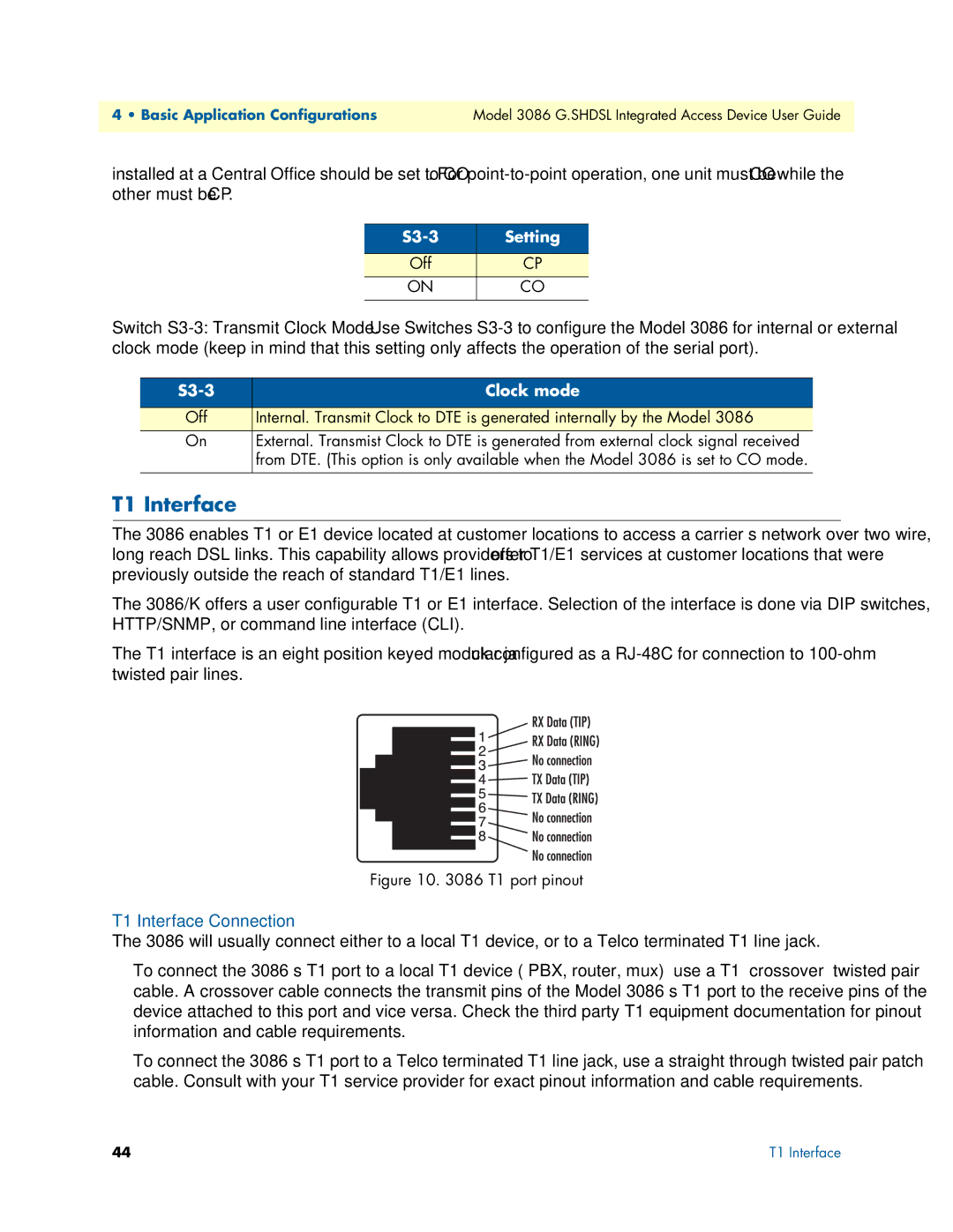
The T1 interface is an eight position keyed modular jack configured as a
Figure 10. 3086 T1 port pinout
T1 Interface Connection
The 3086 will usually connect either to a local T1 device, or to a Telco terminated T1 line jack.
•To connect the 3086’s T1 port to a local T1 device ( PBX, router, mux) use a T1 ‘crossover’ twisted pair cable. A crossover cable connects the transmit pins of the Model 3086’s T1 port to the receive pins of the device attached to this port and vice versa. Check the third party T1 equipment documentation for pinout information and cable requirements.
•To connect the 3086’s T1 port to a Telco terminated T1 line jack, use a straight through twisted pair patch cable. Consult with your T1 service provider for exact pinout information and cable requirements.
44 | T1 Interface |
