Change the Termination Jumpers on a Rear Panel Video BNC Card

In a single-bay, non-looping configuration (up to 256 cameras and 32 monitors), the jumpers must be set in the terminated position. Refer to the Installing Additional Matrix Bays—Sideframing and Downframing section in the Appendix for details on termination jumper settings in multiple- bay configurations.

When looping video out to another device (such as a DVR, VCR, or switcher), set the termination jumpers on the CM9770-RPC cards to the unterminated position.

The termination jumpers are set in the appropriate position when your system is configured at the factory by Pelco. However, if you expand or change your system, or purchase a replacement CM9770-RPC card, you may need to change the termination yourself.

Since the CM9770-RPC consists of two cards assembled together, you must access the termination jumpers on each card in a different way. Access the termination jumpers on the right-side card as shown in Figure 8. Access the termination jumpers on the left-side card as shown in Figure 9.

Figure 13 and Figure 14 illustrate sample sideframing configurations. Figure 15 illustrates a sample downframing configuration.

Refer to the Installing Additional Matrix Bays—Sideframing and Downframing section in the Appendix for detailed instructions on sideframing and downframing.

1

2

3

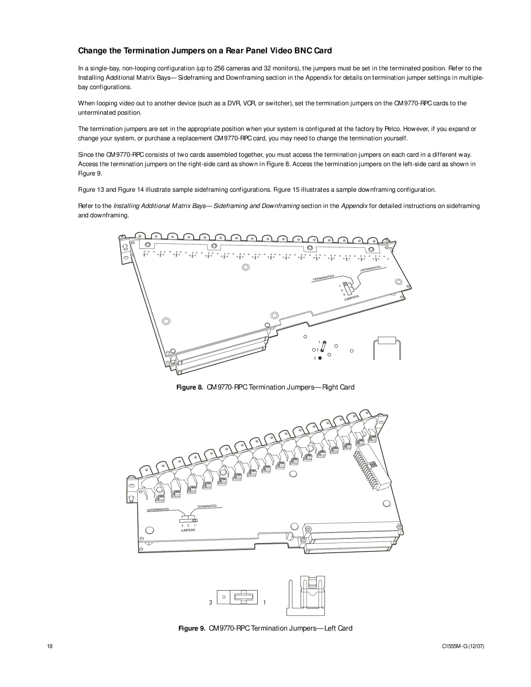
Figure 8. CM9770-RPC Termination Jumpers—Right Card

3

1

Figure 9. CM9770-RPC Termination Jumpers—Left Card

18

C1555M-G (12/07)

Page 18
Image 18
Pelco manual CM9770-RPC Termination Jumpers-Right Card