NETWORKING
Networking of systems is required when the following conditions apply:
•Two or more individual systems need to share video and control features. The
–One or more System 9740 or 9760 systems (note that the
–One or more System 9770 or 9780 systems
•More than 2,048 cameras are required.
•More than 256 monitors are needed for the system (without full
![]() NOTE: When using
NOTE: When using
•Alarms and cameras connected to
The
The NIU offers the following features:
•Each system maintains local operations (local camera switching, control, etc.) if the NIU goes
•A system can be remotely located as far as the transmission type and path allows (typically
•Information on each node connected to the network (for example, cameras and monitors attached) is automatically downloaded to the NIU.
•Operators can be allocated/restricted access to most features/equipment throughout the network.
•Alarm signals can be transferred between nodes.
Refer to the System 9760/9770 Networking Guide for detailed instructions on networking your system. Note that the information in the networking guide is applicable to both the System 9760 and the System 9770, except for the instructions in the Network Setup section, which apply to the old
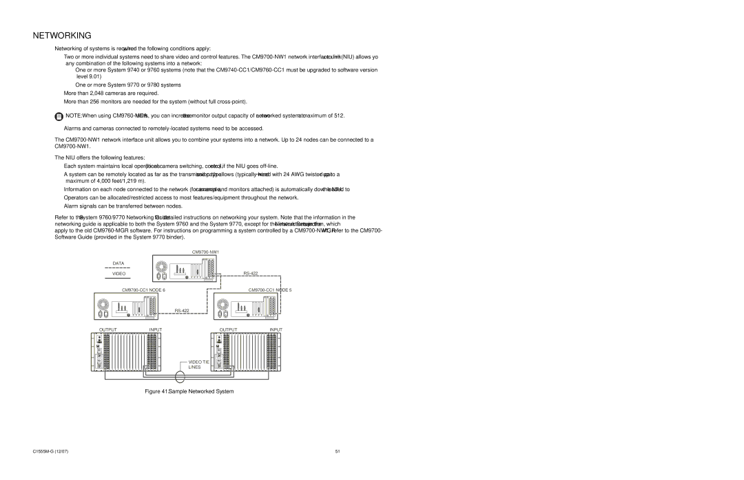
DATA
VIDEO
OUTPUT | INPUT | OUTPUT | INPUT |
VIDEO TIE
LINES
Figure 41. Sample Networked System
51 |