SYSTEM DEVICE CONNECTIONS
1.Turn off power to all system devices and disconnect all power line cords while connecting system devices.
2.Complete the following steps to connect one or more
![]() NOTE:
NOTE:
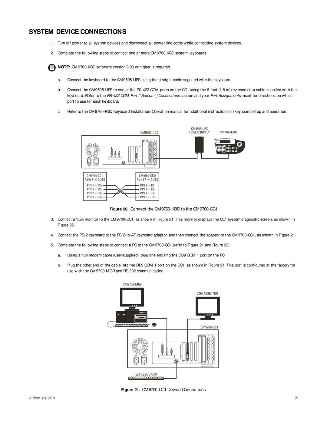
a.Connect the keyboard to the
b.Connect the
c.Refer to the
POWER SUPPLY | ||||||||
|
|
|
|
|
|
|
|
|
|
|
|
|
|
|
|
|
|
|
|
|
|
|
|
|
|
|
|
|
|
|
|
|
|
|
|
|
|
|
|
|
|
|
|
|
PIN 1 = TX+ PIN 2 = TX- PIN 7 = RX- PIN 8 = RX+
PIN 1 = TX+
PIN 2 = TX-
PIN 7 = RX-
PIN 8 = RX+
Figure 20. Connect the CM9760-KBD to the CM9700-CC1
3.Connect a VGA monitor to the CM9700-CC1, as shown in Figure 21. This monitor displays the CC1 system diagnostic screen, as shown in Figure 25.
4.Connect the PS/2 keyboard to the
5.Complete the following steps to connect a PC to the
a.Using a null modem cable
b.Plug the other end of the cable into the DB9 COM 1 port on the CC1, as shown in Figure 21. This port is configured at the factory for use with the
VGA MONITOR
PS/2 KEYBOARD
Figure 21. CM9700-CC1 Device Connections
29 |