Pelco 9770 RS-422 COM PORT “SERCOM” CONNECTIONS, Other peripherals, as necessary, NIU connection

Models: 9770

1 66
Download 66 pages 18.23 Kb
Page 31
Image 31
RS-422 COM PORT (“SERCOM”) CONNECTIONS

RS-422 COM PORT (“SERCOM”) CONNECTIONS

All peripheral equipment in a System 9770 connect through the RS-422 COM ports on the CM9700-CC1 rear panel. (These ports are also known as “sercom” ports, short for “serial communication” ports.) If you exceed the number of CM9700-CC1 rear panel ports available, you can add ports with the CM9700/9760-SER port expander unit.

NOTES:

When connecting peripheral equipment to the serial communication ports, shielded cabling is required to comply with CE emissions guidelines.

Generally, Pelco will preconfigure your 9770 system, and then provide you with a Port Assignment Table. This document identifies which port should be used for each device. Set up your system with the port assignments specified in your Port Assignment Table. The information provided in this section should be used when expanding or servicing your system.

The 9700 System Manager software configures your system with the appropriate hierarchy of connections, so the easiest way to determine where to connect each device is to use the 9700 System Manager to set up your system. The resulting list of devices in the tree view portion of the CM9700-MGR Main window identifies the appropriate port number for each device in your system. Sample device list views are provided in the following tables, to illustrate sample connections for each type of configuration.

Note that a specific hierarchy of connections is required when connecting equipment to the RS-422 COM ports. Connect MXB units into the first available sequential ports, starting with port 5. Do not skip a port number when making MXB connections. Note, however, that the hierarchy varies, depending on whether your system is networked and whether you use the hot switch package to connect a backup CC1 unit. The hierarchy rules are provided in Tables B-E.

Once your MXB units and any NIU (network interface unit) or hot switch devices are connected (refer to Figure 23 and Figure 24), you can then connect peripheral devices (such as keyboards) into any remaining ports. Peripheral devices do not have to be connected in any sequential order, and you can leave ports empty between peripheral devices.

NOTE: In the following tables, “hot switch” refers to using the
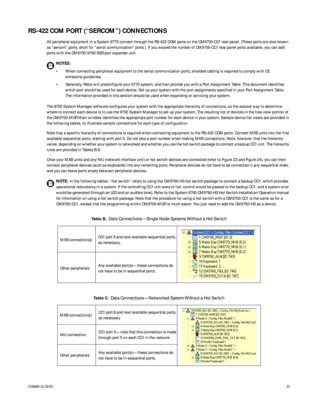
 CM9760-HS hot switch package to connect a backup CC1, which provides operational redundancy in a system. If the controlling CC1 unit were to fail, control would be passed to the backup CC1, and a system error would be generated (through an LED and an audible tone). Refer to the System 9760 CM9760-HS Hot Switch Installation/Operation manual for information on using a hot switch package. Note that the procedure for using a hot switch with a CM9700-CC1 is the same as for a CM9760-CC1, except that the programming within CM9700-MGR is much easier. You just need to add the CM9760-HS as a device.

Table B. Data Connections—Single Node Systems Without a Hot Switch

MXB connection(s)

CC1 port 5 and next available sequential ports, as necessary.

Other peripherals

Any available port(s)—these connections do not have to be in sequential ports.

Table C. Data Connections—Networked System Without a Hot Switch

MXB connection(s)

CC1 port 6 and next available sequential ports,


as necessary.


NIU connection

CC1 port 5—note that this connection is made


through port 5 on each CC1 in the network.


Other peripherals

Any available port(s)—these connections do


not have to be in sequential ports.


C1555M-G (12/07)

31

Page 31
Image 31
Pelco 9770 manual RS-422 COM PORT “SERCOM” CONNECTIONS, Table B. Data Connections-Single Node Systems Without a Hot Switch