Manuals
/
Pelco
/
Photography
/
Security Camera
Pelco
manual
Mounting the CM9770-MXB in AN Open Rack, Mounting the CM9770-MXB in an Open Rack
Models:
9770
1
54
66
66
Download
66 pages
18.23 Kb
51
52
53
54
55
56
57
58
Troubleshooting
Specification
Install
Signal to Noise Ratio 71dBrms
Backslash \ symbol
Connecting Satellite Devices
Monitor Display Problems
Color Diagnostic Check
DOS Commands
Monitor Color Adjustment
Page 54
Image 54
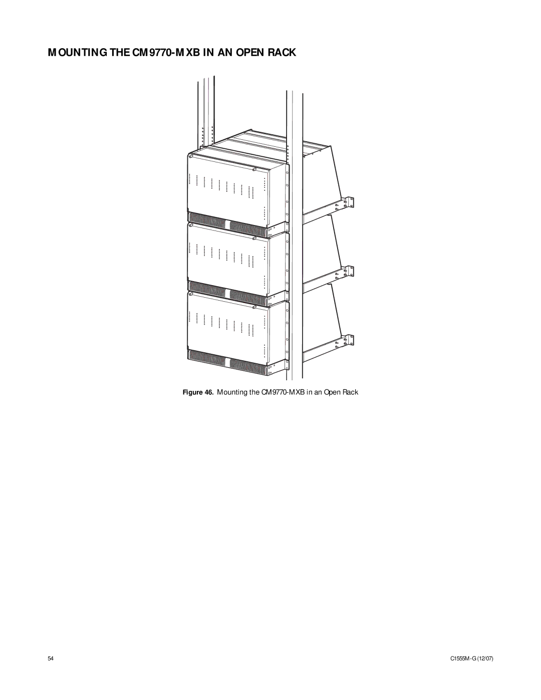
MOUNTING THE
CM9770-MXB
IN AN OPEN RACK
Figure 46.
Mounting the
CM9770-MXB
in an Open Rack
54
C1555M-G
(12/07)
Page 53
Page 55
Page 54
Image 54
Page 53
Page 55
Contents
System
C1555M-G 12/07
Contents
List of Illustrations
List of Tables
Description
Matrix Bay
Models
Controller and CPU Components
Network Interface Unit
Keyboards
Optional Components
Compatible Receivers
CM9700-CC1
Installation
Unpacking
CM9770-MXB
Mounting
CM9770-MXB Mounting Baffle
Mounting the CM9770-MXB on Top of the Mounting Baffle
Mounting the CM9700-CC1
Video INPUT/OUTPUT Connections
Opening the CM9770-MXB Front Cover
Insert or Replace a Video Card
Installing Video Input Cards CM9770-VCC
How to Turn On the Pelco V-Sync Signal
Remove a Video Card
Installing Monitor Output Cards CM9770-VMC
Insert or Replace a Monitor Card
Remove a Monitor Card
Color Diagnostic Check
Performing a Basic LED Check
Table A. LEDs Illuminated During a Basic Check
Installing Rear Panel BNC Cards
Insert or Replace a Rear Panel Video BNC Card CM9770-RPC
Remove a Rear Panel Video BNC Card CM9770-RPC
CM9770-RPC Termination Jumpers-Right Card
Looping Video
Looping Video Out from the CM9770-MXB
Insert or Replace a Rear Panel Monitor BNC Card CM9770-RPM
Video INPUT/OUTPUT Capacity
Single Bay
Multiple Bays, Single Node
Sample Sideframing System Using an Output Bay
Sample Single-Node System with Downframing
Networked System
Sample Networked System
Power Supply Module CM9700-MPS
Install a Backup Power Supply
Remove a Backup Power Supply
HOW to Replace the Fuse in a Power Supply Module
How to Replace a Power Supply Fuse
HOW to Turn OFF the Audible Power Supply Alarm
Power Supply Alarm Speaker Switch
System Device Connections
CM9700-CC1 Device Connections
CM9700-MGR PC Pin-Out Detail
RS-422 COM Port Sercom Connections
As necessary NIU connection
Not have to be in sequential ports
Switch NIU connection
Table D. Data Connections-Single Node, Hot-Switched System
Switch
MXB connections
Sample CM9770-MXB to CM9700-CC1 Connection
System Start-Up
Initialize the CC1
Verify System Operation
Initialize Keyboards
Monitor Color Adjustment
Display the CM9770-MXB Software Version Level
Display a Blue Raster Screen
Programming Your System
Getting Help Using CM9700-MGR
Sample Wizard
Operation
Operating Your System
HOW to Expand Your System
Appendix
System Architecture
Sideframing
Downframing
Downframing with DFC Cards
Downframe Cards
DFC Card
HOW to Install or Replace a CM9700-SER Card in the CC1
ISA Slot Number W1 IRQ Setting
How to Install a CM9700-SER Card
When LED Is On
Video Input Card CM9770-VCC Detail
Color When LED is on or blinking
Monitor Output Card CM9770-VMC Detail
Port 1 RS-422 Baud Rate
Test Mode
Color System
Data Protection
Networking
Connecting Satellite Devices
Programming Satellite Devices
HOW to Install Video Patch Panels CM9700-VPP
CM9700-VPP Vertical Mount
Mounting the CM9770-MXB in AN Open Rack
Mounting the CM9770-MXB in an Open Rack
AUTOEXEC.BAT and the Boot Process
DOS Environment and Command Reference
Boot Process
Invoking the CM9700 Executable
Navigating the DOS Directory Tree
DOS Commands
File Names and DOS
Example PATH=c\c\dosc\windows
Example
Using the Wild Card Character
Manipulating Files in the DOS Environment
Change to the 9700 directory
DOS Reference
\CD
Backslash \ symbol
Help command
Floppy of a disk formatted using this switch
By default, DOS searchers just the current directory
Symptom Possible Cause Corrective Action
Troubleshooting
Problems with the CC1
VCC Card CF LED Is Illuminated and the AUX LED Is Blinking
Switch
Monitor Display Problems
LED Indicators on the Power Supply Module
Front Panel Label Color
Specifications
Input Voltage
Differential Gain 51% Differential Phase Degrees
Signal to Noise Ratio 71dBrms
Communication
Regulatory Notices
CM9780-MXB
Product Warranty and Return Information
ISO9001
Top
Page
Image
Contents