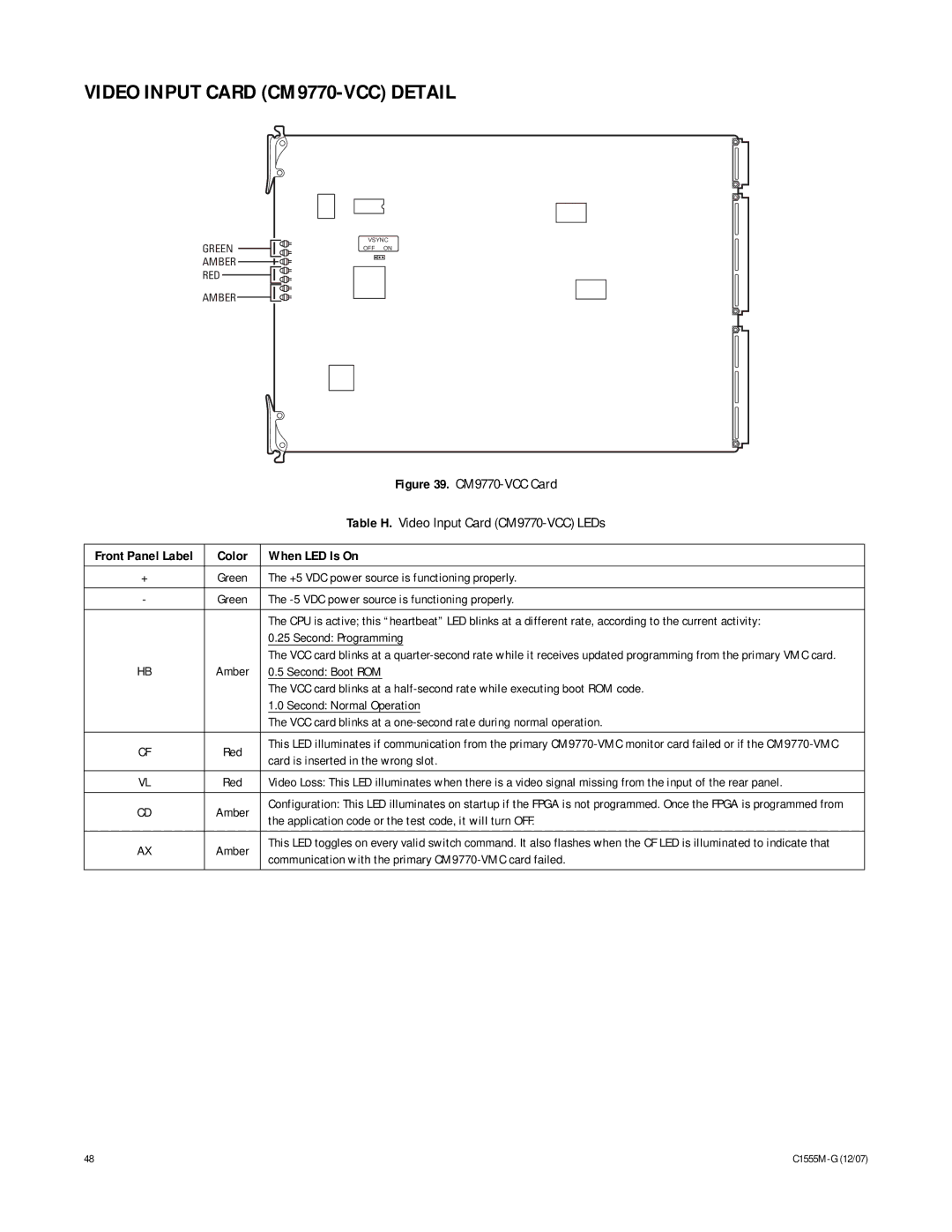
VIDEO INPUT CARD (CM9770-VCC) DETAIL
GREEN ![]()
![]() AMBER
AMBER ![]()
![]()
![]()
![]()
![]() RED
RED ![]()
![]()
AMBER
VSYNC
OFF ON
|
| Figure 39. | |
|
| Table H. Video Input Card | |
|
|
| |
Front Panel Label | Color | When LED Is On | |
|
|
| |
+ | Green | The +5 VDC power source is functioning properly. | |
|
|
| |
- | Green | The | |
|
|
| |
|
| The CPU is active; this “heartbeat” LED blinks at a different rate, according to the current activity: | |
|
| 0.25 Second: Programming | |
|
| The VCC card blinks at a | |
HB | Amber | 0.5 Second: Boot ROM | |
|
| The VCC card blinks at a | |
|
| 1.0 Second: Normal Operation | |
|
| The VCC card blinks at a | |
|
|
| |
CF | Red | This LED illuminates if communication from the primary | |
card is inserted in the wrong slot. | |||
|
| ||
|
|
| |
VL | Red | Video Loss: This LED illuminates when there is a video signal missing from the input of the rear panel. | |
|
|
| |
CD | Amber | Configuration: This LED illuminates on startup if the FPGA is not programmed. Once the FPGA is programmed from | |
the application code or the test code, it will turn OFF. | |||
|
| ||
|
|
| |
AX | Amber | This LED toggles on every valid switch command. It also flashes when the CF LED is illuminated to indicate that | |
communication with the primary | |||
|
| ||
|
|
|
48 |
|