Step 1: Basic Recorder Connections (continued)
English
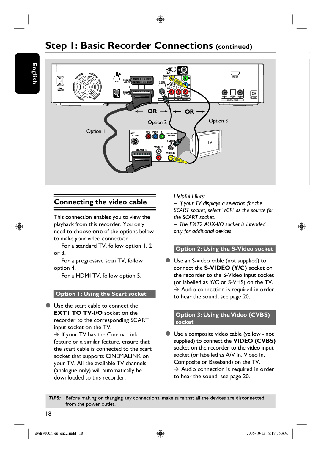
Option 1
OR 
 OR
OR 
Option 2 | Option 3 |
| |
| TV |
Connecting the video cable
This connection enables you to view the playback from this recorder. You only need to choose one of the options below to make your video connection.
–For a standard TV, follow option 1, 2 or 3.
–For a progressive scan TV, follow option 4.
–For a HDMI TV, follow option 5.
Option 1: Using the Scart socket
Use the scart cable to connect the EXT1 TO
If your TV has the Cinema Link feature or a similar feature, ensure that the scart cable is connected to the scart socket that supports CINEMALINK on your TV. All the available TV channels (analogue only) will automatically be downloaded to this recorder.
Helpful Hints:
–If your TV displays a selection for the SCART socket, select ‘VCR’ as the source for the SCART socket.
–The EXT2
Option 2: Using the S-Video socket
Use an
Audio connection is required in order to hear the sound, see page 20.
Option 3: Using the Video (CVBS) socket
Use a composite video cable (yellow - not supplied) to connect the VIDEO (CVBS) socket on the recorder to the video input socket (or labelled as A/V In, Video In, Composite or Baseband) on the TV.
Audio connection is required in order to hear the sound, see page 20.
TIPS: Before making or changing any connections, make sure that all the devices are disconnected from the power outlet.
18
dvdr9000h_eu_eng2.indd 18