5 • Optical Mark Recognition (OMR)
OMR Specifications
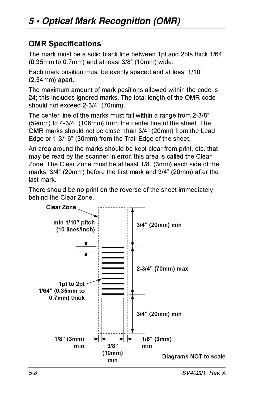
The mark must be a solid black line between 1pt and 2pts thick 1/64” (0.35mm to 0.7mm) and at least 3/8” (10mm) wide.
Each mark position must be evenly spaced and at least 1/10” (2.54mm) apart.
The maximum amount of mark positions allowed within the code is 24; this includes ignored marks. The total length of the OMR code should not exceed
The center line of the marks must fall within a range from
An area around the marks should be kept clear from print, etc. that may be read by the scanner in error, this area is called the Clear Zone. The Clear Zone must be at least 1/8” (3mm) each side of the marks, 3/4” (20mm) before the first mark and 3/4” (20mm) after the last mark.
There should be no print on the reverse of the sheet immediately behind the Clear Zone.
Clear Zone
min 1/10” pitch |
|
|
| 3/4” (20mm) min | ||||
(10 lines/inch) |
|
|
| |||||
|
|
|
|
| ||||
|
|
|
|
|
|
|
|
|
|
|
|
|
|
|
|
|
|
|
|
|
|
|
|
|
|
|
|
|
|
|
|
|
|
|
|
|
|
|
|
|
|
|
|
|
|
|
|
|
|
|
|
|
|
|
|
|
|
|
|
|
|
|
1pt to 2pt ![]()
![]() 1/64” (0.35mm to
1/64” (0.35mm to
0.7mm) thick
|
|
|
|
|
|
|
| 3/4” (20mm) min | ||
|
|
|
|
|
|
|
|
|
|
|
1/8” (3mm) |
|
|
|
|
|
|
|
| 1/8” (3mm) | |
|
|
|
|
|
|
|
| |||
|
|
| 3/8” |
| ||||||
min |
|
|
|
|
|
| min | |||
|
|
| (10mm) |
|
|
|
| Diagrams NOT to scale | ||
|
|
|
| min |
|
|
|
| ||
|
|
|
|
|
|
|
|
| ||
SV40221 Rev. A |