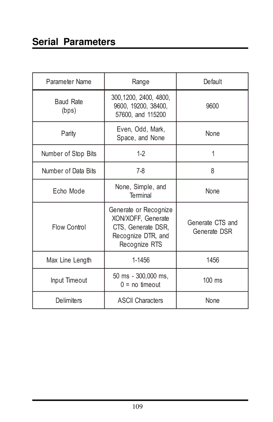
User’s Guide
RangeLAN2 Serial Adapter
Models 7910 and
Copyright
Limited Warranty, Disclaimer, Limitation Of Liability
Trademarks
FCC WARNING
Warranty Return Policy
Configuration
Contents
Quick Installation
3. Wireless Topologies
B. Serial Adapter TCP/IP Specification
10. Advanced Configuration Menu
14. Troubleshooting
A. Packetized Mode Specification
D. Parameters
E. Procedure for Downloading New Software
G. How to Reach Technical Support
H. U.S. Specifications
1. Introduction
The RangeLAN2 Family
The Product Package
System Requirements
RangeLAN2 791x Serial Adapter Components
2. Quick Installation
Attachment of the RangeLAN2 Serial Adapter Antenna
4. Each RangeLAN2 791x Serial Adapter is preconfigured to use Domain 0. If you have multiple pairs of Serial Adapters and each pair consists of one Master and one Station, set each pair to a unique Domain number. Using the Domain rotary switch on the underside of the RangeLAN2 Serial Adapter, set each pair to a unique Domain number from 0-8 to ensure minimal interfer- ence. If you decide to use Domain 8, refer to Chapter 5 for information concerning this switch setting’s role in the Pairing Domain communication feature
Page
Point-to-Point
3. Wireless Topologies
Point-to-Point Topology
Page
Point-to-Multipoint
Point-to-Multipoint
Point-to-Point Using RangeLAN2 Infrastructure
Point-to-Multipoint Using a RangeLAN2 Access Point as a Base Unit
Figure 6 above shows a simple configuration of this topology. Desktop 1 is on the same network as a RangeLAN2 Access Point. Serial Adapters 1 and 2 are configured as Stations and are synchronized to the Access Point, which is configured as a Master. Desktop 1 is running a custom-made application written in a programming interface, such as Windows Sockets, which uses TCP/IP to communicate with either or both Serial Adapters
4. Pass-through and Packetized Modes
Page
5. Understanding the Hardware Rotary Switches
Rotary Switches
Domain Switch
The Pairing Domain
1. Ensure that both units are turned off
LED Indicators
Status LED
Serial LED
Radio LED
Top Panel LEDs
791x Serial Adapter
There are also four LEDs on the back panel of the RangeLAN2
Back Panel LEDs
Override LED Master LED Sync LED
Serial Port Specification
Mounting Options
Antenna Options
Mounting Holes
2.75” 2.10”
Page
Displaying the Configuration Menu
6. Configuration
Page
The following six chapters detail the sub-menus, shown above
Page
7. Radio Configuration Menu
t Only visible when configured as a Station
Radio Parameters
Default
Only visible when configured as a Master
Page
In order to establish communications, all Stations and the Master must be configured with the same Domain number. Radios on different Domains cannot communicate with each other. The Domain is a software filter which does not affect the actual radio frequency or the frequency hopping sequence
Page
For example, you can use Channel 1, Subchannel 1 for Adapter Pair A and Channel 1, Subchannel 2 for Adapter Pair B. The two pairs will not communicate with one another. However, they are still sharing the 1.6 Mbps pipe since they are both using Channel
Page
There is no inactivity timeout set by default, but you may change this to any interval of 10 seconds. This parameter is visible only when the Serial Adapter is set as a Station. A Master unit does not have a sleep mode
You may choose to disable a Serial Adapter’s ability to roam with the Roaming Enabled parameter. This feature is enabled by default however, if you want a RangeLAN2 Serial Adapter to communicate with one and only one other RangeLAN2 product, you may disable this feature
Page
The software tree below shows the options available
8. Network Configuration Menu
Range
Network Parameters
Default
Parameter Name
Page
cate with the wired infrastructure, it will be necessary to change the default address to one which is on the same subnet as the wired stations so that IP packets are routed correctly. You can override the default address using the IP Address option in the configuration menu. This parameter will not change unit the Serial Adapter is reset
9. Serial Configuration Menu
Even, Odd, Mark
Serial Parameters
Echo Mode
Remote Serial Adapter
Local Serial Adapter
Page
Page
Page
10. Advanced Configuration Menu
Range
Advanced Parameters
Default
Parameter Name
Page
Page
Page
Page
11. Display Parameter Values
Reset Parameters to Factory Defaults Radio Configuration Menu
Baud R ate configured # S top Bits configured Max. Line Length
P arity configured # Data Bits configured Line Delimiters
Advanced Configuration Parameters
12. View Statistics
Radio Statistics
Serial Errors Statistics
Packetized Mode Statistics
TCP/IP Statistics
Microwave Ovens
13. Performance Hints
Range
The antenna should be placed in a vertical position
How to Obtain Help with Your Installation
14. Troubleshooting
LED Error Codes
7 blinks Failed to initialize the TCP/IP stack
Commonly Asked Technical Support Questions
3 blinks Software error 4 blinks Failed to initialize the radio
5 blinks Memory full 6 blinks Miscellaneous error
bring up the software configuration
1. Verify that your terminal settings
2. Ensure that you are using a RS
allow users to configure the Serial
Overview
A. Packetized Mode Specification
Pass-through Versus Packetized Mode
MCP Modem Command Protocol PPX-1 Proxim Packet Exchange RS-232
Higher layer error correcting
The table below summarizes the features of the PPX-1 layer 2 protocol
Error Detection
Error Correction
PPX-1 Protocol
Modem Command Protocol MCP
Transmit Data Packet
MCP Command Messages to the Serial Adapter
Request Serial Adapter Version
Request Radio Signal Strengths
Initialize Serial Adapter
Go To Standby
Set Radio Channel
Set Baud Rate
Set Network Subchannel
Get RS-232 Pin Status
Station Search
Override RangeLAN2 Parameters
Call up Configuration Menu
Data Packet Received
MCP Responses From Serial Adapter
Status Indication of Transmitted Packet
Signal Strength Report
Standby Confirmation
Serial Adapter Version Report
Initialization Confirmation
Subchannel Confirmation
Radio Channel Confirmation
Station Search Reply
Baud Rate Confirmation
RangeLAN2 Parameter Confirmation
RS-232 Pin Status Reply
B. Serial Adapter TCP/IP Specification
Bit 1 is set if DSR is asserted on the sending side
BYTE 1 Packet type 0= point-to-point UDP or TCP, or 1= broadcast
BYTES 2 and 3 Packet length
The pin status byte includes the following information
Bit 6 Reserved and always set to Bit 7 Reserved and always set to
Bit 4 is set if CD is asserted on the sending side
Stevens, W. Richard, UNIX Network Programming Networking
Sample TCP Receive Program
Sample TCP/IP Communication Programs
51 perror“getting socket name” 52 exit4
27 if !logfile 28 printf“Error Couldn’t open log file\n” 29 exit1
35 perror“opening stream socket” 36 exit2
44 perror“binding stream socket” 45 exit3
65 /* Establish the TCP connection. Accept returns a new
Sample TCP Send Program
74 ifwrite sock, buf, dataLength+4 75 perror“Sending $QUIT message”
49 the remote machine 50 printf“Connecting...\n”
52 perror“Connecting stream socket” 53 exit1
67 perror“Sending stream message”
Sample UDP Receive Program
Sample UDP Send Program
22 long npackets= 23 char buf1024 24 struct sockaddrin name
39 perror“opening datagram socket” 40 exit1
13 #define DATA1 15 mainargc, argv 16 int argc 17 char *argv
19 int i, sock 20 short dataLength 21 short networkDataLength
55 name.sinfamily= AFINET
C. Menu Structure
S erial Adapter Main Menu Display P arameter Values Radio Parameters
S eria l Adapte r M ain M e nu D ispla y Pa ra m e ter V alues
R em ote Port Num ber
IP Address
Subnet M ask
Local Port Num ber
S erial Adapte r M a in M e nu Display Param eter V alues
S e rial Ad ap te r M ain M en u D isplay Pa ra m e te r V a lue s
Serial E rro rs F ram in g Parity Overru n
Parameter Name
D. Parameters
Default
Radio Parameters
Range
Default
Network Parameters
Parameter Name
Range
Default
Serial Parameters
Parameter Name
Range
Advanced Configuration Parameters
Default
Parameter Name
E. Procedure for Downloading New Software
Page
F. Glossary
Inhibit - To set a flow control pin to the “off” position
G. How to Reach Technical Support
H. U.S. Specifications
Index
Page
24. See also LEDs
23. See also LEDs
XMODEM 111 XON/OFF. See Flow Control
U.S. Specifications 116-117 UDP 46, 64
View Statistics
Windows Sockets. See Sockets