tions where developing special software to interact with the Serial Adapter is undesirable.
For some applications, the
For the External Computer to be able to send both data and commands to the Serial Adapter, both the Serial Adapter and the External Computer must agree on some rules of order for distin- guishing data packets from command packets. Proxim has de- fined a simple serial protocol which performs this function. This protocol is incorporated into the packetized mode of the firmware. The remainder of this document is devoted to an explanation of the Packetized mode serial protocol.
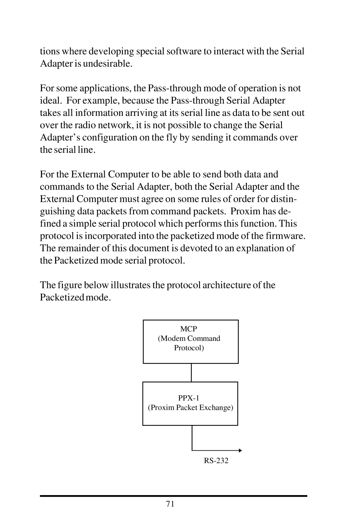
The figure below illustrates the protocol architecture of the Packetized mode.
MCP
(Modem Command
Protocol)
(Proxim Packet Exchange)
71