Chapter 1. Installation Requirements
1.1 Application
This specification is applied to the DDP70 Printer for Unpacking, Installing andAdjustment.
1.2 Installation Area
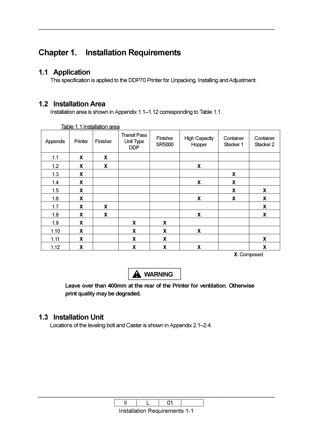
Installation area is shown in Appendix
Table 1.1 Installation area
|
|
| Transit Pass | Finisher | High Capacity | Container | Container | |
Appendix | Printer | Finisher | Unit Type | |||||
SR5000 | Hopper | Stacker 1 | Stacker 2 | |||||
|
|
| DDP | |||||
|
|
|
|
|
|
| ||
|
|
|
|
|
|
|
| |
1.1 | X | X |
|
|
|
|
| |
1.2 | X | X |
|
| X |
|
| |
1.3 | X |
|
|
|
| X |
| |
1.4 | X |
|
|
| X | X |
| |
1.5 | X |
|
|
|
| X | X | |
1.6 | X |
|
|
| X | X | X | |
1.7 | X | X |
|
|
|
| X | |
1.8 | X | X |
|
| X |
| X | |
1.9 | X |
| X | X |
|
|
| |
1.10 | X |
| X | X | X |
|
| |
1.11 | X |
| X | X |
|
| X | |
1.12 | X |
| X | X | X |
| X | |
|
|
|
|
|
| X: Composed | ||
![]()
![]() WARNING
WARNING
Leave over than 400mm at the rear of the Printer for ventilation. Otherwise print quality may be degraded.
1.3 Installation Unit
Locations of the leveling bolt and Caster is shown in Appendix
II
L
010
Installation Requirements
