RuggedRouter
Ruggedrouter User Guide
How To Use This User Guide
About this User Guide
Applicable Firmware Revision
Who Should Use This User Guide
Document Conventions
Quick Start Recommendations
Basic Web Based Configuration
Additional Configuration
About this User Guide
Table Of Contents
Table Of Contents
RuggedRouter User Guide
100
114
144
Page
Table Of Contents
Page
241
Page
RuggedRouter Setup Main Menu
Table Of Figures
Scheduled Commands Displaying a Command
T1/E1 Network Interfaces After Interface Creation
Adsl Link Statistics
Show Public Key
Link Backup Status 162
Raw Socket Menu
IRIGB/IEEE1588 General Configuration menu 230
255
IAS Window Edit Profile 282
Setting Up And Administering The Router
Access Methods
Accounts And Password Management
Default Configuration
Accessing The RuggedRouter Command Prompt
RuggedRouter Setup Shell
Configuring Passwords
From the Console Port
Configuring IP Address Information
Setting The Hostname
Configuring Radius Authentication
Radius Server Configuration menu
Enabling And Disabling The SSH and Web Server
Configuring The Date, Time And Timezone
Enabling And Disabling The Gauntlet Security Appliance
Displaying Hardware Information
RuggedRouter Hardware Information Menu
Restoring a Configuration
Selecting a configuration to reload
Using a Web Browser to Access the Web Interface
RuggedRouter Web Interface
SSL Certificate Warnings
Structure of the Web Interface
RuggedRouter Web Interface Main Menu Window
Using The LED Status Panel
LED Status Panel
Obtaining Chassis Information
LED Name Description
Webmin Configuration
Webmin Configuration Menu
IP Access Control
Ports And Addresses
Change Help Server
Webmin Configuration Menu, Logging
Logging
Authentication
Webmin Configuration Menu, Authentication
Webmin Events Log
Webmin Events Log
This page intentionally blank
Configuring The System
Bootup And Shutdown
Change Password Command
Scheduled Commands
Scheduled Commands Displaying a Command
Scheduled Cron Jobs
Webmin Scheduled Cron Jobs
System Hostname
System Time
Configuring Networking
Network Configuration
Core Settings
Dummy Interface
Default Route Table
Configured Static Routes
Routing And Gateways
Manually Entered Static Routes
Static Multicast Routing
Static Multicast Routing
End To End Backup
DNS Client
Host Addresses
Page
Configuring End To End Backup
Current Routing & Interface Table
Configuring Ethernet Interfaces
Ethernet Interface Fundamentals
Vlan Interface Fundamentals
LED Designations
PPPoE On Native Ethernet Interfaces Fundamentals
RuggedRouter Functions Supporting VLANs
Ethernet
Ethernet Interfaces
Editing Currently Active Interfaces
Editing a Network Interface
Edit Boot Time Interfaces
Virtual Interfaces
Virtual Lan Interfaces
PPPoE On Native Ethernet Interfaces
List PPPoE Interfaces
Edit PPPoE Interface
Editing a PPPoE Interface
PPP Logs
Current Routes & Interface Table
Configuring Frame Relay/PPP And T1/E1
T1/E1 Fundamentals
Frame Relay
T1/E1
Location Of Interfaces And Labeling
Included With T1E1
T1/E1 Network Interfaces
Strategy For Creating Interfaces
Editing a T1/E1 Interface
Naming Of Logical Interfaces
T1 Settings
E1 Settings
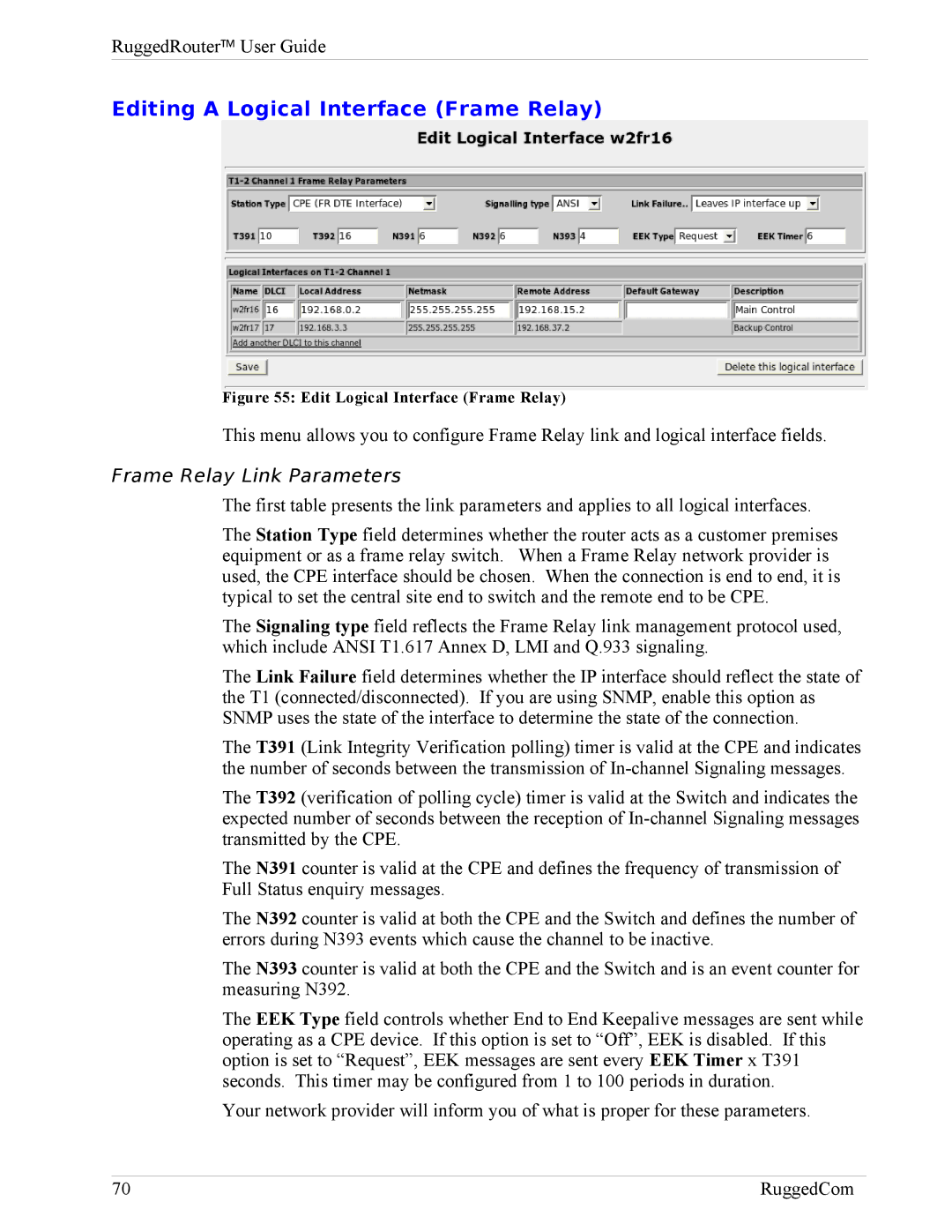
Editing a Logical Interface Frame Relay
Frame Relay Link Parameters
Editing a Logical Interface PPP
Frame Relay DLCIs
T1/E1 Statistics
Link Statistics
Frame Relay Interface Statistics
Frame Relay Statistics
PPP Interface Statistics
PPP Link Statistics
T1/E1 Loopback
T1/E1 Loopback Menu
Upgrading Software
Upgrading Firmware
Configuring Frame Relay/PPP And T3
T3 Fundamentals
T3 Configuration
T3 Network Interfaces
Editing a T3 Interface
Edit T3 Interface
T3 Statistics
Upgrading Software
Page
Configuring Frame Relay/PPP
DDS Fundamentals
DDS Configuration
DDS Network Interfaces
Edit Logical Interface Frame Relay, single Dlci
DDS Statistics
DDS Link Statistics
DDS Loopback
Frame Relay And PPP Interface Statistics
Page
Configuring PPPoE/Bridged Mode On
PPPoE/Bridged Mode Fundamentals
Adsl Fundamentals
Authentication, Addresses and DNS Servers
PPPoE MTU Issues
Bridged Mode
Adsl Configuration
Adsl Network Interfaces
Editing a Logical Interface PPPoE
Editing a Logical Interface Bridged
Edit Logical Interface Bridged
Adsl Statistics
Adsl Link Statistics
Current Routes & Interface Table
Configuring PPP and Modem
PPP Mode Fundamentals
When the Modem Connects
Modem Fundamentals
Modem Configuration
Modem Main Menu
Blind dial
Modem PPP Client Connections
Modem PPP Client
Modem PPP Server
Modem Incoming Call Logs
Modem PPP Logs
PPP Logs
Modem PPP Connection Logs
PPP Connection Logs
Page
Configuring The Firewall
Firewall Fundamentals
Stateless vs Stateful Firewalls
Linux netfilter, iptables And The Shoreline Firewall
Network Address Translation
Shorewall Quick Setup
Port Forwarding
ShoreWall Terminology And Concepts
Zones
Interfaces
Hosts
Policy
Masquerading And Snat
Interface Subnet Address Protocol Ports
Rules
Reject
Configuring The Firewall And VPN
Route Based Virtual Private Networking
Policy Based Virtual Private Networking
Virtual Private Networking To a DMZ
Firewall Main Menu
Starting Shorewall Firewall Menu
Shorewall Firewall Menu
Network Zones
Network Interfaces
Editing a Firewall Network Interfaces
Network Zone Hosts
Firewall Zone Hosts
Default Policies
Masquerading
Firewall Rules
Editing a Masquerading Rule
Static NAT
Static NAT
Actions When Stopped
Creating a Static NAT Entry
Page
Page
Configuring An IPsec VPN
VPN Fundamentals
IPsec Modes
Policy Vs Route Based VPNs
Supported Encryption Protocols
Public Key And Pre-shared Keys
Other Configuration Supporting IPSec
X509 Certificates
NAT Traversal
Openswan Configuration Process
VPN Main Menu Before Key Generation
VPN Main Menu
IPsec and Router Interfaces
Page
Server Configuration
IPsec VPN Configuration After Connections Have Been Created
Public Key
Preshared Keys
List Certificates
VPN Connections
IPsec VPN Connection Details
Page
Left/Right Systems Settings
Export Configuration
Showing IPsec Status
IPsec Status
IPSec X.509 Roaming Client Example
Select a Certificate Authority
VPN Networking Parameters Client Configuration
Router IPSec Configuration
Generate X.509 Certificates
Firewall IPSec Configuration
Ethernet Port Configuration
Page
Configuring Dynamic Routing
Quagga, RIP and Ospf
RIP Fundamentals
Ospf Fundamentals
Key Ospf And RIP Parameters
Link State Advertisements
Network Areas
Active/Passive Interface Default
Router-ID
Hello Interval and Dead Interval
Redistributing Routes
Configuring Ospf Link Costs
Ospf Authentication
RIP Authentication
Link Detect
Administrative Distances
Ospf And Vrrp Example Network
Area And Subnets
Vrrp Operation
Enable Protocols
Dynamic Routing
Core
Core Global Parameters
Core Interface Parameters
View Core Configuration
Ospf
Ospf Global Parameters
Page
Ospf Interfaces
Ospf Interfaces
View Ospf Configuration
Ospf Network Areas
Ospf Status
RIP Global Parameters
RIP Global Parameters
RIP Interfaces
RIP Key Chains
RIP Networks
RIP Networks
View RIP Configuration
RIP Status
Page
Configuring Link Backup
Link Backup Fundamentals
Path Failure Discovery
Link Backup Main Menu
Link Backup Configuration
Use Of Routing Protocols And The Default Route
Edit Link Backup Configuration
Link Backup Logs
Link Backup Status
Test Link Backup
Page
Page
Configuring Vrrp
Problem With Static Routing
Vrrp Solution
Vrrp Fundamentals
Vrrp Example
Page
Vrrp Configuration
Vrrp Main Menu
Editing a Vrrp Instance
Vrrp Instance
Viewing Vrrp Instances Status
Vrrp Instances Status
Configuring Traffic Prioritization
Traffic Prioritization Fundamentals
Priority Queues
Filters
TOS Prioritization
Included With Traffic Prioritization
Prioritization Example
Traffic Prioritization Main Menu
Interface Prioritization Menu
Prioritization Queues
Prioritization Filters
Prioritization Transmit Queue Length
Prioritization Statistics
Prioritization Statistics
Configuring Generic Routing Encapsulation
GRE Fundamentals
GRE Configuration Menu
GRE Main Menu
Page
Network Utilities
Network Utilities Main Menu
Ping Menu
Traceroute Menu
Host Menu
Trace Menu
Tcpdump a Network Interface
Frame Relay Link Layer Trace a WAN Interface
Serial Trace a Serial Server Port
Interface Statistics Menu
Interface Statistics Menu
Current Routing & Interface Table
Current Routing & Interface Table
Interface Status
Page
Configuring Serial Protocols
Serial IP Port Features
Serial Protocols Applications
Character Encapsulation
RTU Polling
Broadcast RTU Polling
Serial Protocols Concepts And Issues
Host And Remote Roles
Use Of Port Redirectors
Message Packetization
Use of Turnaround Delays
Serial Protocols Main Menu
Port Settings Menu
Assign Protocols Menu
RawSocket Menu
Page
Protocol Specific Packet Error Statistics
Serial Protocols Statistics Menu
Serial Protocols Trace Menu
Serial Protocols Trace Menu
Serial Protocols Sertrace Utility
Is provided
Page
Configuring Goose Tunnels
IEC61850 Goose Fundamentals
Layer 2 Tunnel Daemon Details
Layer 2 Tunnels Main Menu
Layer 2 Tunnels Main Menu
General Configuration Menu
Goose Tunnels Menu
Goose Statistics Menu
Activity Trace Menu
Page
Page
Configuring The Dhcp server
Dhcp Fundamentals
Dhcp Network Organizations
Dhcp Client Options
Page
Option 82 Support with Disable NAK
Example Dhcp Scenarios And Configurations
Single Network With Option82 Clients On One Switch
Single Network With Dynamic IP Assignment
Single Network With Static IP Assignment
Page
Page
Dhcp Server Main Menu
Dhcp Server Menu
Dhcp Shared Network Configuration
Dhcp Shared Network Configuration
Dhcp Subnet Configuration
Dhcp Subnet Configuration
Dhcp Group Configuration
Dhcp Host Configuration
Dhcp Pool Configuration
Dhcp Pool Configuration
Configuring NTP
NTP Fundamentals
NTP Sanity Limit
NTP And The Precision Time Protocol Card
Included With NTP
NTP Server Main Menu
Generic Options
Servers Configuration
Peers Configuration
Viewing The NTP Status
Viewing The NTP Log
Viewing The GPS Status
Viewing The GPS Log
Configuring SSH
SSH Fundamentals
Included With SSH
SSH Main Menu
SSH Server
Access Control
Networking
Page
Configuring Irigb And IEEE1588
IEEE1588 Fundamentals
PTP Network Roles
PTP Master Election
Irigb Fundamentals
Synchronizing NTP from IEEE1588
Irigb Output Formats
GPS Cable compensation
Reference Clocks
How The Router Selects a Reference Clock
General Configuration
IRIGB/IEEE1588 Main Menu
Irigb Configuration
IEEE1588 Configuration
Irigb Status
IEEE1588 Status
Irigb Log
Page
Configuring The Snort IDS
Snort Fundamentals
Which Interfaces To Monitor
Snort Rules
Global Configuration
Snort IDS Main Menu
Performance And Resources
Network Settings
Rulesets
Rule Lookup by SID
PreProcessors
Alerts & Logging
Edit Config File
Maintaining The Router
Alert System
Alert Menu
Alert Configuration
Alert Configuration Menu
Alert Filter Configuration
Alert Definition Configuration
Change Alert Definition
Page
Gauntlet Security
What And How Gauntlet Protects
Gauntlet And The Firewall
Gauntlet Status Menu
Upgrading Gauntlet
Backup And Restore
System Backup And Restore
General Configuration Setup
Archive Backup
Archive History
Archive Restore
Archive Difference Tool
Archive Differences List
Snmp Configuration
Show Difference for selected file between two targets
Snmp Configuration Main Menu
System Configuration
Network Addressing Configuration
Access Control page, Snmp V1 and V2c
250 RuggedCom
Trap Configuration
Trap Configuration page, Trap Options
MIB Support
RuggedRouter supports the following MIBs
Radius Authentication
Radius Authentication Configuration
Edit Radius Server Parameters
Outgoing Mail
Chassis Parameters
Parameter Description
Syslog Factory Defaults
System Logs
Remote Logging
Changing a Syslog entry to remote log
Upgrade System
RuggedRouter Software Fundamentals
When a Software Upgrade Requires a Reboot
Automatic Upgrade
Upgrade to RX1100
Change Repository Server
Automatic Upgrading
Upgrading All Packages
Installing a New Package
Pre-upgrade/Post-upgrade scripts
Uploading And Downloading Files
Upload/Download menu
Security Considerations
Security Actions
Page
Appendix a Setting Up a Repository
Initial Repository Setup
Repository Server Requirements
Setting Up The Routers
Upgrading The Repository
An Alternate Approach
Upgrading Considerations
Appendix B Downgrading Router Software
Appendix C Installing Apache Web Server On Windows
Apache Default Web
Page
Appendix D Installing IIS Web Server On Windows
Installing IIS
Appendix E Radius Server Configuration
Windows Internet Authentication Service
FreeRadius
Edit Profile window, Click Add... button
276 RuggedCom
RuggedCom 277
Index
Dhcp
Goose
NTP
SSH
Vrrp