APPENDIX B Connectors
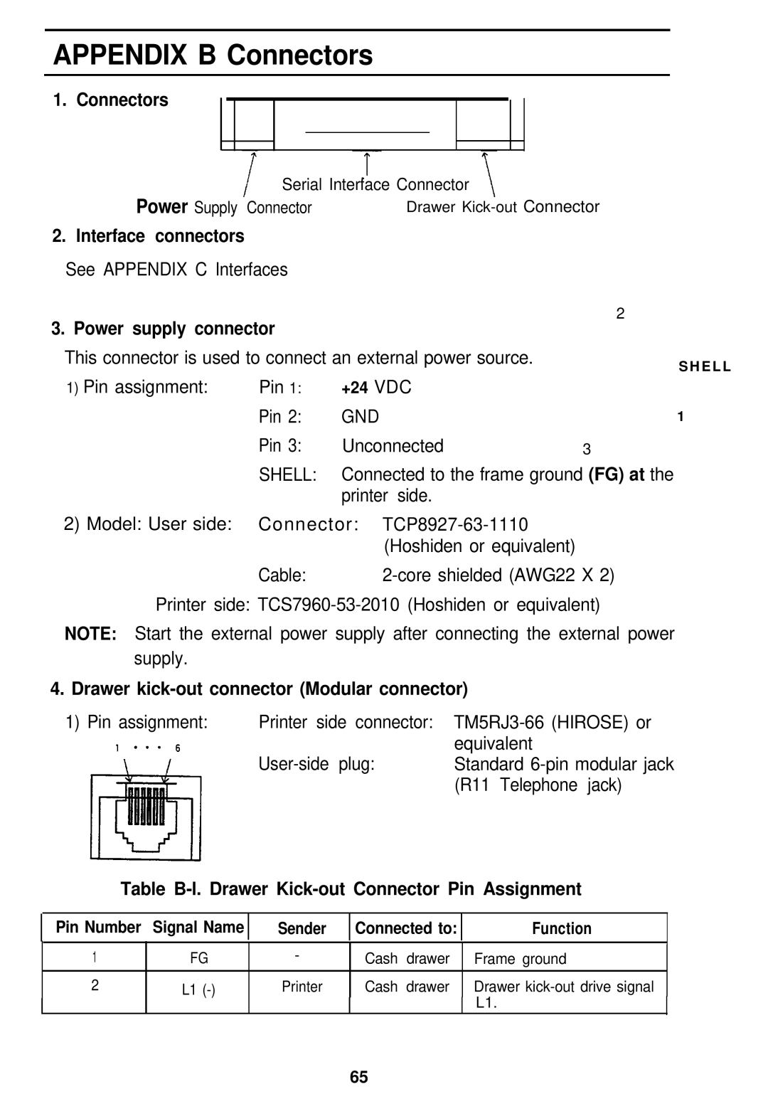
1. Connectors
Serial Interface Connector
Power Supply Connector | Drawer |
2. Interface connectors
See APPENDIX C Interfaces
3. Power supply connector
This connector is used to connect an external power source.
2
S H E L L
1) Pin assignment: | Pin 1: | +24 VDC |
|
| Pin 2: | GND | 1 |
| Pin 3: | Unconnected | 3 |
| SHELL: | Connected to the frame ground (FG) at the | |
|
| printer side. |
|
2)Model: User side: Connector:
Cable: |
Printer side:
NOTE: Start the external power supply after connecting the external power supply.
4. Drawer kick-out connector (Modular connector)
1) Pin assignment: | Printer side connector: | |
| equivalent | |
| Standard | |
|
| (R11 Telephone jack) |
Table B-l. Drawer Kick-out Connector Pin Assignment
Pin Number Signal Name
Sender
Connected to:
Function
1 | FG | - | Cash | drawer | Frame ground |
|
| ||||||
|
|
|
|
|
|
|
2 | L1 | Printer | Cash | drawer | Drawer |
|
|
|
|
|
| L1. |
|
65