T M - L 6
Operator’s Manual
thermal line printer
400179501
Page
CC CLASS A FCC COMPLIANCE STATEMENT FOR AMERICAN USERS
FOR CANADIAN USERS
INTRODUCTION
APPENDIX
CONTENTS
About this manual
APPENDIX D Character Code Tables APPENDIX E Command Summary
5-1 Panel Switches and Commands
APPENDIX A General Specifications
5-2 Printable Area and Label Paper Conditions
1. SETTING UP
n Maintenance
1-1 Checking the Contents of the Box
Chapter 1 Unpacking the Printer
g Checking the parts
1-2 Choosing a Place for the Printer
1-3 Removing the Protective Material
n Part names
1-4 Names and Functions of Parts
À Â Ã Ä
POWER green
Panel switches
POWER
ERROR red
n Plugging in AC adapter
Chapter 2 Before Setting Up
2-1 Connecting the Power Supply to the Printer
CAUTIONS
n Connecting the interface cable
2-2 Connecting the Host Computer to the Printer
Serial Interface Cable Drawer Kick-out Connector
n Installing the roll paper
Chapter 3 Installing the Parts
3-1 Installing the Roll Paper
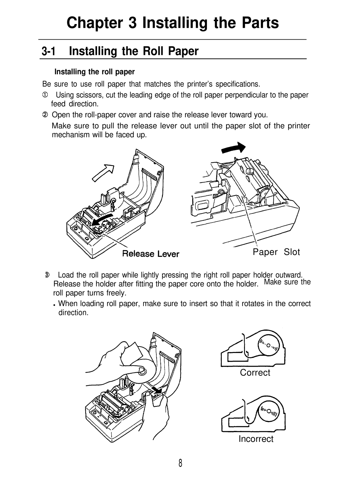
Paper Slot
Tear-off -Edge
Table 3-l. Adjustment Values of the Paper-end Detector
3-2 Adjusting the Paper-end Detector
n How to adjust the paper-end detector
Adjustment
After adjusting, ensure that the detector operates smoothly
n Setting the DIP switches
3-3 Setting the DIP Switches
n Locating the DIP switches
Table 3-4. Print Density Selection
n DIP-Switch Functions Table 3-2. DIP-switch Functions
Table 3-3. Baud Rate Selection
DIP SW
n The purpose of the self test
Chapter 4 The Self Test
4-1 Checking Operation with the Self Test
n The self test checks the following
II. REFERENCE
n Switches 1 Power switch
Chapter 5 Cautions while Using the Printer
5-1 Panel Switches and Commands
2 Paper-feed switch
n Printable area
5-2 Printable Area and Label Paper Conditions
Hole dimensions
Label paper
n Notes on printing and paper feeding
5-3 Miscellaneous Notes
When all the characters on one line are rotated
Table 5-2. Required Paper Feed Amount Dots
n Notes on handling thermal paper and label paper
n Notes on the power supply
n Notes on handling the printer mechanism
5-4 Error Correction
n ERROR LED red
inserting paper
Table 5-3. Error Display
be inspected
Table 5-4. Command Standby State Display
5-5 Cleaning the Head
n Cleaning the head
n The cover-open detector
5-6 The Cover-open Detector
5-7 Removing Jammed Paper
n How to use this table
Chapter 6 Software Control
n Controlling the printer with commands
6-1 Printer Control
Range
6-2 Command Descriptions
6-3 Commands HT
n Command descriptions XXX Command
Range
ESC SP n
ESC ! n
Range
ESC E, ESC F, ESC
ESC $ n1 n2
Range
ESC ¥
Range
ESC % n
ESC & s n m ap s Xam-n+l
n =
k = n 1 + 2 5 6 X n 2 m = 0
ESC * m n1 n2 d k
m = 0, 1, 32
k = n 7 + 2 5 6 X n 2 X 3 m = 3 2 , 3
l The bit image modes selectable by m are as follows
Range
ESC 3 n
ESC = n
Range
Clears the data in the print buffer and resets the printer mode to
ESC @
ESC D nkNUL
Range
ESC E n
Range
Range
ESC G n
ESC J n
Range
Range
ESC R n
ESC V n
Range
ESC a n
ESC ¥ n1 n2
ESC - n
Range
Position
ESC c 4 n
Range
ESC d n
ESC p m n1 n2
ESC c 5 n
Range
Connector pin
ESC t n
ESC u n
Range
Undefined
V a l u e
ESC n
Range
Range
GS FF
GS*n1n2dn1xn2x8
GS/m
Range
GS A m n
Range
FF, GS FF
GS C 0 m n
Range
0 ≤ n ≤
m = 3 , n = O
GS C1 n1 n2 n3 n4 n5 n6
Range
m=3, n=1
T o s t o p c o u n t i n g
GS C2 n1 n2
Range
Stops counting if n1 + n2 x 256 = n3 + n4 x 256, n5 = 0, or n6 =
n1 + n2 x 256 =
GSC N1 N2 N3 N4 N5
Range
W i t h c o u n t i n g u p
Range
GS H n
GS c
With counting down
Range
GS f n
GS h n
Range
Code
GS w n
GS k n d k NUL
Range
blinks and the printer waits for the paper feed switch to
GS n1 n2 n3
After waiting the period specified by n2, the error LED
If this command is received while defining the macro, the macro
1. Introduction
6-4 Program Descriptions
3. How to write program 3-1. Printing on the roll paper
2. Before printing
170 PRINT #l, CHR$27 “! CHR$0 180 PRINT #l , “ABCDEFGHIJK” CHR$
120 PRINT #1, “ABCDEF” CHR$
150 PRINT #l , CHR$27 “! CHR$48 160 PRINT #l , “ABCDEFGHIJK” CHR$
characters per line
GS H n
The 12 characters, “012345678901” are print data
g Sample Program onto thermal paper
3-2. Printing on label paper
230 CLOSE #1
n Sample Program onto thermal label paper
180 PRINT #1, CHR$29 ”c”
1. Printing specifications
APPENDIX A General Specifications
APPENDIX
2. Characters specifications
Font A
Default
Character structure
12 x 24 includes the horizontal
4.2 Thermal label paper
10. External dimensions and weight
6. Electrical characteristics
7. EMI by using Epson PS-130
8. Reliability
2. Interface connectors
APPENDIX B Connectors
1. Connectors
3. Power supply connector
Electrical characteristics
Figure B-2. Drawer Kick-out Signal Interface Circuit
APPENDIX C Interfaces
Figure B-1. Drawer Kick-out Drive Signal
1. Specifications RS-232C compatible
2. Interface connector terminal assignments and signal functions
3. Serial interface timing
Page
Page
International character set
Name
APPENDIX E Command Summary
Command
GS C
Command
Name
GS C2