Overview
BRU-H700 HD Optical Multiplex Unit (not supplied)
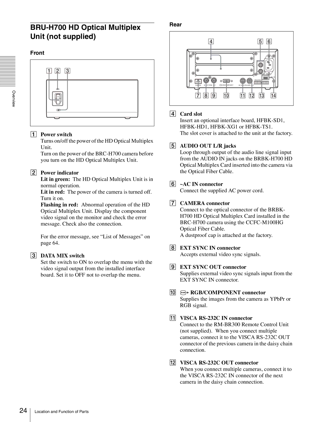
Front
1 2 3
APower switch
Turns on/off the power of the HD Optical Multiplex Unit.
Turn on the power of the
BPower indicator
Lit in green: The HD Optical Multiplex Unit is in normal operation.
Lit in red: The power of the camera is turned off. Turn it on.
Flashing in red: Abnormal operation of the HD Optical Multiplex Unit. Display the component video signal on the monitor and check the error message. Check also the connection.
For the error message, see “List of Messages” on page 64.
CDATA MIX switch
Set the switch to ON to overlap the menu with the video signal output from the installed interface board. Set it to OFF not to overlap the menu.
Rear
4 |
| 5 6 | |
|
| AUDIO OUT |
|
|
| L |
|
|
| R |
|
|
| FUNCTION ~AC IN | |
|
| 1 | 6 |
|
| VISCA |
|
CAMERA IN EXT SYNC OUT | RGB/COMPONENT | IN VISCA |
|
7 8 9 | 0 | qa qs qd | qf |
DCard slot
Insert an optional interface board,
The slot cover is attached to the unit at the factory.
EAUDIO OUT L/R jacks
Loop through output of the audio line signal input from the AUDIO IN jacks on the
F~AC IN connector
Connect the supplied AC power cord.
GCAMERA connector
Connect to the optical connector of the BRBK- H700 HD Optical Multiplex Card installed in the
A dustproof cap is attached at the factory.
HEXT SYNC IN connector Accepts external video sync signals.
IEXT SYNC OUT connector
Supplies external video sync signals input from the EXT SYNC IN connector.
J![]() RGB/COMPONENT connector
RGB/COMPONENT connector
Supplies the images from the camera as YPbPr or RGB signal.
KVISCA RS-232C IN connector
Connect to the
LVISCA RS-232C OUT connector
When you connect multiple cameras, connect it to the VISCA
24
Location and Function of Parts