SYSTEM Menu
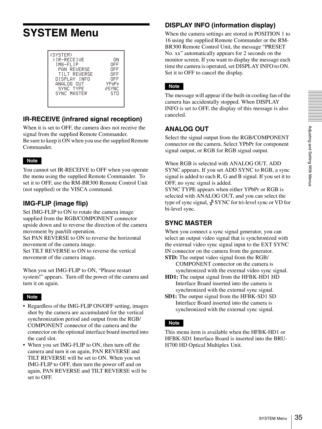
<SYSTEM> |
|
|
|
|
| |
|
|
| ON | |||
|
|
| OFF | |||
PAN | REVERSE |
|
|
| OFF | |
TILT | REVERSE |
|
|
| OFF | |
DISPLAY | INFO |
|
|
| OFF | |
ANALOG | OUT |
| YPBPR | |||
SYNC | TYPE |
|
|
| SYNC | |
SYNC | MASTER |
|
|
| STD | |
IR-RECEIVE (infrared signal reception)
When it is set to OFF, the camera does not receive the signal from the supplied Remote Commander.
Be sure to keep it ON when you use the supplied Remote Commander.
Note
You cannot set
IMG-FLIP (image flip)
Set
Set PAN REVERSE to ON to reverse the horizontal movement of the camera image.
Set TILT REVERSE to ON to reverse the vertical movement of the camera image.
When you set
Note
•Regardless of the
•When you set
DISPLAY INFO (information display)
When the camera settings are stored in POSITION 1 to 16 using the supplied Remote Commander or the RM- BR300 Remote Control Unit, the message “PRESET No. xx” automatically appears for 2 seconds on the monitor screen. If you want to display the message each time the camera is operated, set DISPLAY INFO to ON. Set it to OFF to cancel the display.
Note
The message will appear if the
ANALOG OUT
Select the signal output from the RGB/COMPONENT connector on the camera. Select YPbPr for component signal output, or RGB for RGB signal output.
When RGB is selected with ANALOG OUT, ADD SYNC appears. If you set ADD SYNC to RGB, a sync signal is added to each R, G and B signal. If you set it to OFF, no sync signal is added.
SYNC TYPE appears when either YPbPr or RGB is selected with ANALOG OUT, and you can select the type of sync signal, ![]()
![]()
![]() SYNC for
SYNC for
SYNC MASTER
When you connect a sync signal generator, you can select an output video signal that is synchronized with the external video sync signal input to the EXT SYNC IN connector on the camera from the generator.
STD: The output video signal from the RGB/ COMPONENT connector on the camera is synchronized with the external video sync signal.
HD1: The output signal from the
SD1: The output signal from the
Note
This menu item is available when the
Adjusting and Setting With Menus
SYSTEM Menu
35