OEXT SYNC IN connector Accepts external video sync signals.
PCard slot
Insert an optional interface board,
The slot cover is attached to the camera at the factory.
Q![]() RGB/COMPONENT connector
RGB/COMPONENT connector
Supplies the images as analog component (YPbPr or RGB) signal.
RDATA MIX switch
Set the switch to ON to overlap the menu with the video signal output from the installed interface board. Set it to OFF not to overlap the menu.
SCable cover
The cable cover is attached to the camera at the factory. To remove the cable cover, see page 50.
Note
Do not carry the camera by holding the cable cover. Otherwise, the cable cover may come off and the camera may fall.
Bottom
w; wa ws
TCeiling bracket mounting screw holes
When you install the camera to the ceiling, secure the supplied ceiling bracket to these holes using the supplied four screws. The four feet are attached to the holes at the factory.
For installation, see “Installing the Camera on the Ceiling” on page 52.
UTripod screw holes
When you install the camera to a tripod, secure the tripod to these holes.
VBOTTOM switches
Used for the output signal format selection, RS-
For details, see “Setting of the BOTTOM switches” on page 19.
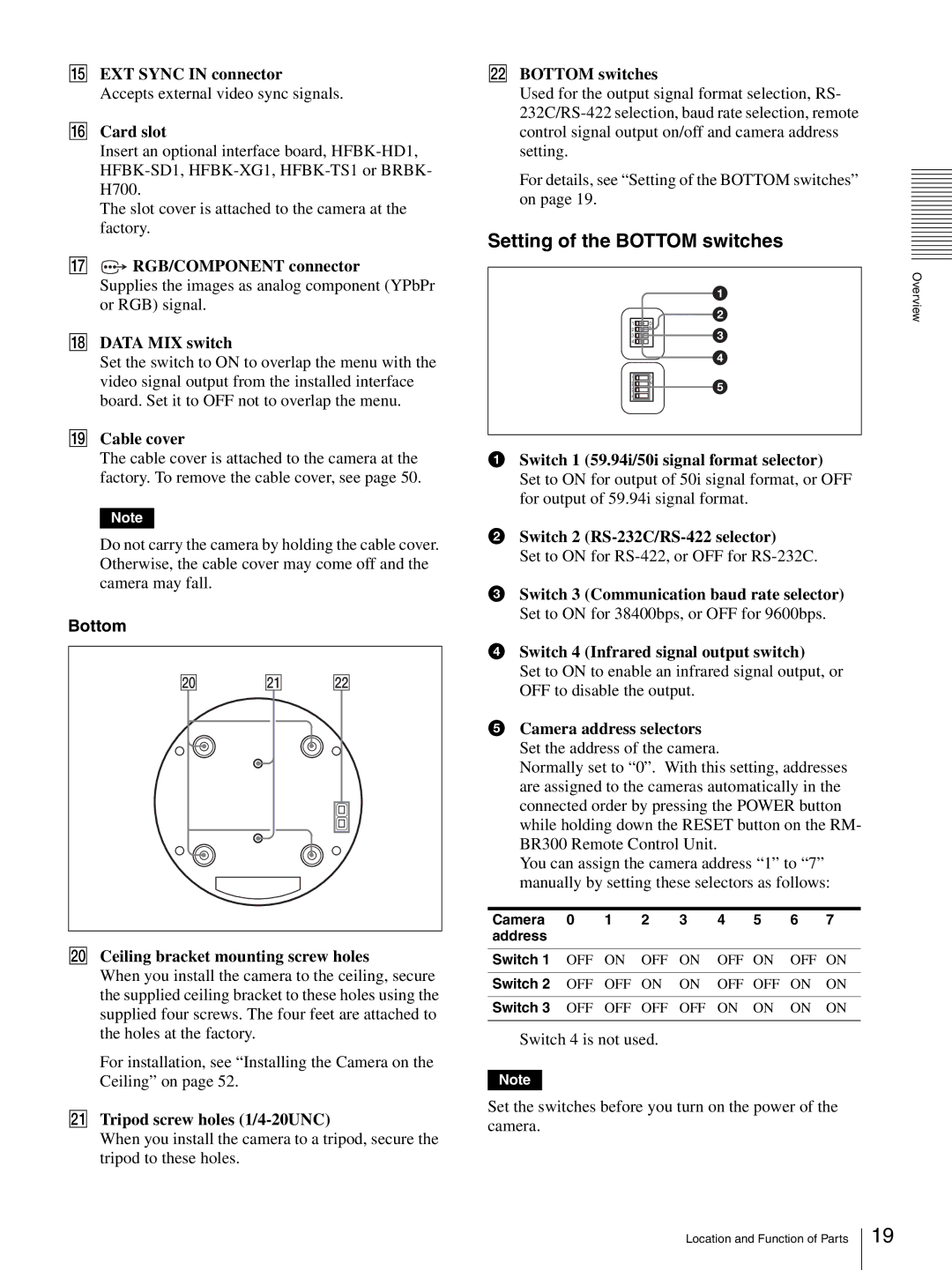
Setting of the BOTTOM switches
|
| 1 |
1 | O | 2 |
| ||
2 | N | 3 |
4 |
| |
3 |
|
|
|
| 4 |
1 | O | 5 |
3 | N | |
2 |
| |
4 |
|
|
1Switch 1 (59.94i/50i signal format selector) Set to ON for output of 50i signal format, or OFF for output of 59.94i signal format.
2Switch 2 (RS-232C/RS-422 selector)
Set to ON for
3Switch 3 (Communication baud rate selector) Set to ON for 38400bps, or OFF for 9600bps.
4Switch 4 (Infrared signal output switch)
Set to ON to enable an infrared signal output, or OFF to disable the output.
5Camera address selectors Set the address of the camera.
Normally set to “0”. With this setting, addresses are assigned to the cameras automatically in the connected order by pressing the POWER button while holding down the RESET button on the RM- BR300 Remote Control Unit.
You can assign the camera address “1” to “7” manually by setting these selectors as follows:
Camera | 0 | 1 | 2 | 3 | 4 | 5 | 6 | 7 |
address |
|
|
|
|
|
|
|
|
|
|
|
|
|
|
|
|
|
Switch 1 | OFF | ON | OFF | ON | OFF | ON | OFF | ON |
|
|
|
|
|
|
|
|
|
Switch 2 | OFF | OFF | ON | ON | OFF | OFF | ON | ON |
|
|
|
|
|
|
|
|
|
Switch 3 | OFF | OFF | OFF | OFF | ON | ON | ON | ON |
|
|
|
|
|
|
|
|
|
Switch 4 is not used.
Note
Set the switches before you turn on the power of the camera.
Overview
Location and Function of Parts
19