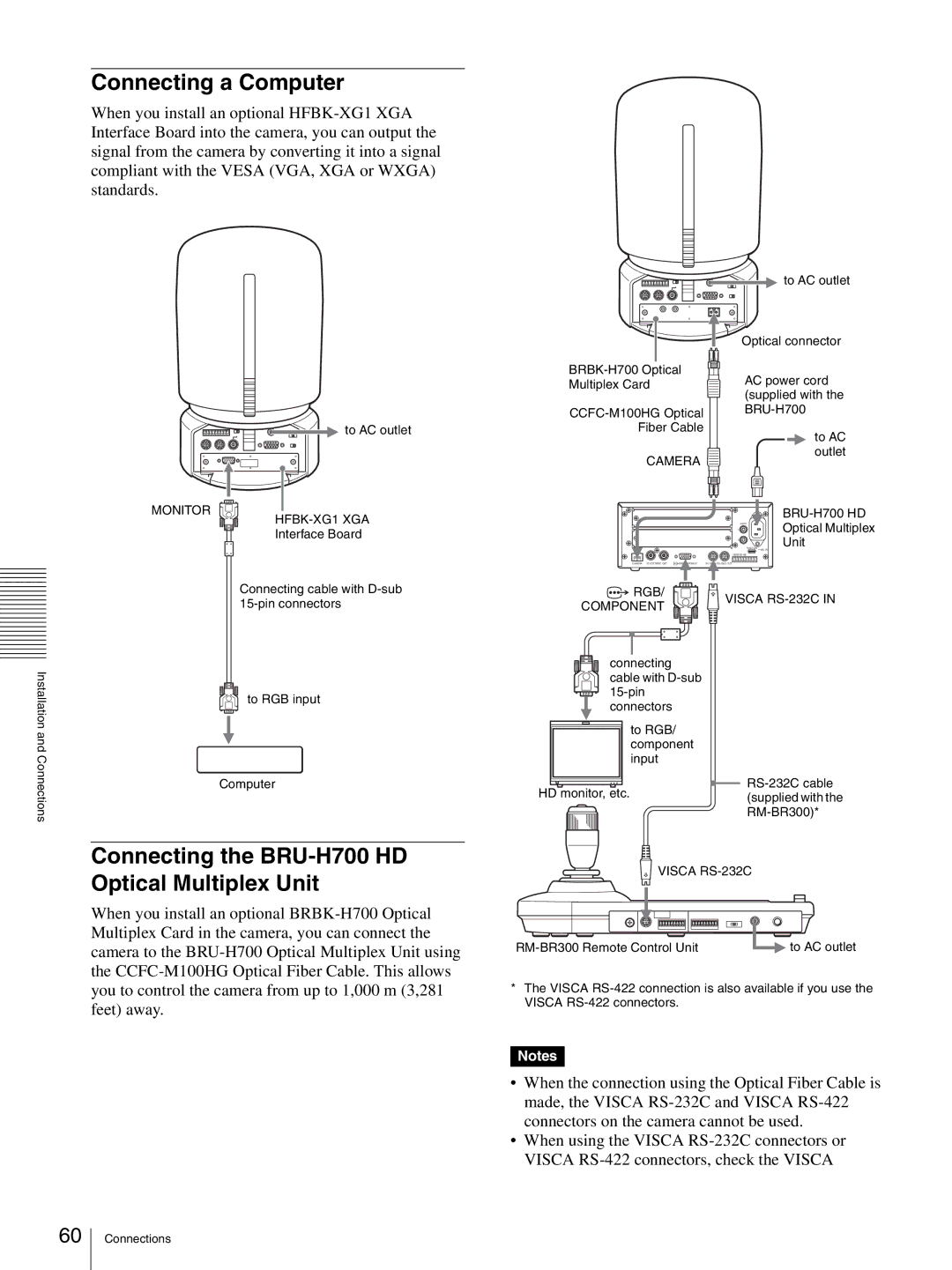
Connecting a Computer
When you install an optional
![]()
![]() to AC outlet
to AC outlet
MONITOR
HFBK-XG1 XGA
Interface Board
| to AC outlet | |
| Optical connector | |
AC power cord | ||
Multiplex Card | ||
(supplied with the | ||
| ||
| ||
Fiber Cable |
|
to AC
outlet
CAMERA
BRU-H700 HD
![]()
![]() L AUDIO
L AUDIO ![]()
![]() Optical Multiplex
Optical Multiplex
R![]() Unit
Unit
FUNCTION ~
1 ![]() 6
6
VISCA
CAMERA IN EXT SYNC OUT | IN |
AC IN
Connecting cable with
Installationand | to RGB input |
| |
Connections | Computer |
|
![]() RGB/
RGB/
COMPONENT
connecting cable with
to RGB/ component input
HD monitor, etc.
![]() VISCA
VISCA
![]()
Connecting the BRU-H700 HD Optical Multiplex Unit
When you install an optional
![]() VISCA
VISCA
to AC outlet |
*The VISCA
Notes
•When the connection using the Optical Fiber Cable is made, the VISCA
•When using the VISCA
60
Connections