Installation and Connections
Installation
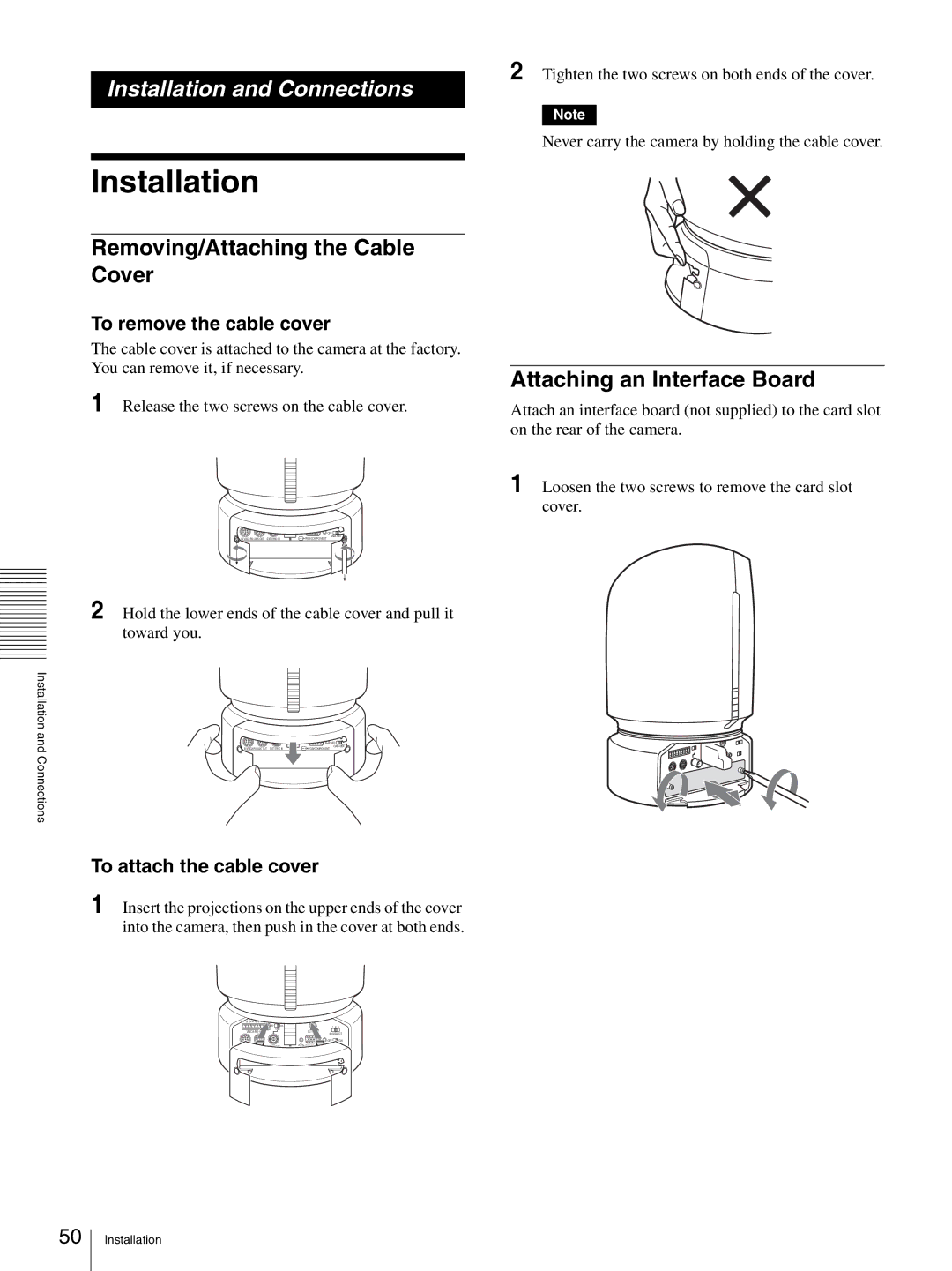
Removing/Attaching the Cable Cover
To remove the cable cover
The cable cover is attached to the camera at the factory. You can remove it, if necessary.
1 Release the two screws on the cable cover.
1 2 3 4 5 6 7 8 9
OFF | ON | 1 | 2 3 |
75 |
|
|
|
VISCA |
| DC IN 12V |
|
|
| IR SELECT | |
|
| OFF | ON |
IN VISCA |
| DATA MIX | |
R | RGB/COMPONENT |
| |
2 Hold the lower ends of the cable cover and pull it toward you.
2 Tighten the two screws on both ends of the cover.
Note
Never carry the camera by holding the cable cover.
Attaching an Interface Board
Attach an interface board (not supplied) to the card slot on the rear of the camera.
1 Loosen the two screws to remove the card slot cover.
Installation and Connections
1 2 3 4 5 6 7 8 9
OFF | ON |
75 |
|
VISCA |
|
IN VISCA | R |
1 2 3
DC IN 12V
IR SELECT
![]() OFF
OFF![]() ON
ON
DATA MIX
RGB/COMPONENT
To attach the cable cover
1 Insert the projections on the upper ends of the cover into the camera, then push in the cover at both ends.
1 2 3 4 5 6 7 8 9
OFF | ON | 1 | 2 3 |
75 |
|
|
|
VISCA |
| DC IN 12V |
|
|
| IR SELECT | |
|
| OFF | ON |
IN VISCA |
| DATA MIX | |
R | RGB/COMPONENT |
| |
50
Installation
