Overview
Location and Function of Parts
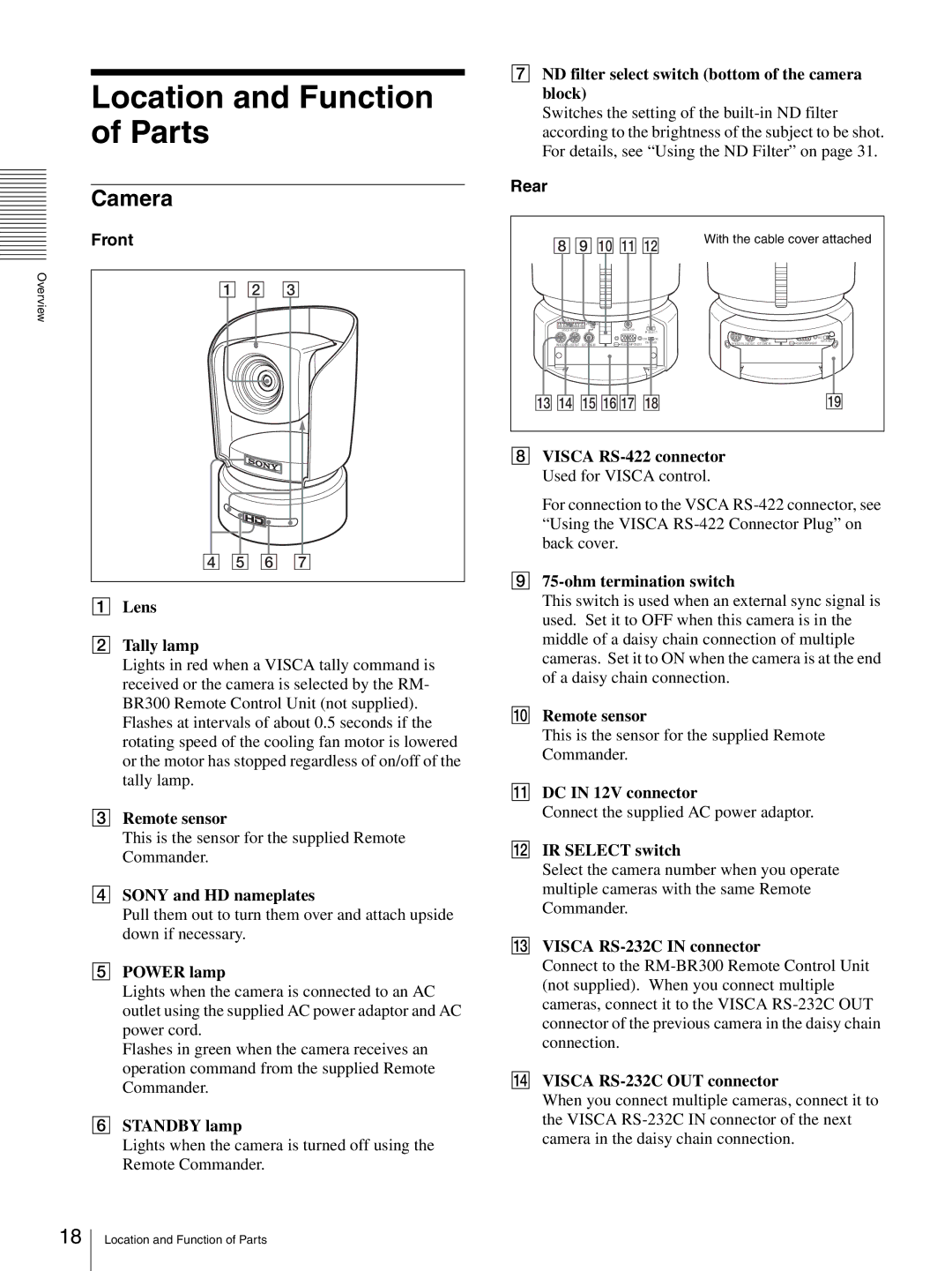
Camera
Front
1 2 3
4 5 6 7
ALens
BTally lamp
Lights in red when a VISCA tally command is received or the camera is selected by the RM- BR300 Remote Control Unit (not supplied).
Flashes at intervals of about 0.5 seconds if the rotating speed of the cooling fan motor is lowered or the motor has stopped regardless of on/off of the tally lamp.
CRemote sensor
This is the sensor for the supplied Remote Commander.
DSONY and HD nameplates
Pull them out to turn them over and attach upside down if necessary.
EPOWER lamp
Lights when the camera is connected to an AC outlet using the supplied AC power adaptor and AC power cord.
Flashes in green when the camera receives an operation command from the supplied Remote Commander.
FSTANDBY lamp
Lights when the camera is turned off using the Remote Commander.
GND filter select switch (bottom of the camera block)
Switches the setting of the
Rear
89 0 qa qs | With the cable cover attached | ||
|
|
| |
|
|
|
|
|
|
|
|
|
|
|
|
|
|
|
|
|
|
|
|
|
|
|
|
|
|
|
|
|
|
|
|
|
|
|
|
|
|
|
|
|
|
|
|
|
|
|
|
|
|
|
|
1 2 3 4 5 6 7 8 9 |
|
|
| 1 2 3 4 5 6 7 8 9 |
|
|
|
OFF | ON | 1 2 | 3 | OFF | ON | 1 2 | 3 |
75 |
|
|
| 75 |
|
|
|
VISCA |
| DC IN 12V |
| VISCA |
| DC IN 12V |
|
|
| IR SELECT |
|
| IR SELECT | ||
|
| OFF | ON |
|
| OFF | ON |
IN VISCA |
| DATA MIX | IN VISCA |
| DATA MIX | ||
R | RGB/COMPONENT |
| R | RGB/COMPONENT |
| ||
qdqf qgqhqj qk | ql |
HVISCA
For connection to the VSCA
I75-ohm termination switch
This switch is used when an external sync signal is used. Set it to OFF when this camera is in the middle of a daisy chain connection of multiple cameras. Set it to ON when the camera is at the end of a daisy chain connection.
JRemote sensor
This is the sensor for the supplied Remote Commander.
KDC IN 12V connector
Connect the supplied AC power adaptor.
LIR SELECT switch
Select the camera number when you operate multiple cameras with the same Remote Commander.
MVISCA RS-232C IN connector
Connect to the
NVISCA RS-232C OUT connector
When you connect multiple cameras, connect it to the VISCA
18
Location and Function of Parts