4.Operation
4.3.4.Diagnostic and Normal Status Displays
This clause describes LED displays while the drive is starting up. When the power is turned on, the drive will go through its diagnostics to reach normal status. When a failure is detected during diagnostics, the LEDs show that the drive is out of order and needs to be repaired.
4.3.4.1. Diagnostic Status Display
The drive starts with its Diagnostic function. This is made up of the Front Panel Test and the Kernel Test.
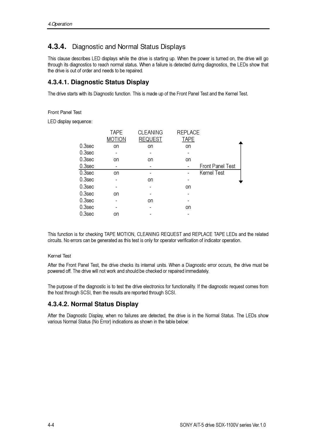
Front Panel Test |
|
|
|
|
LED display sequence: |
|
|
|
|
| TAPE | CLEANING | REPLACE |
|
| MOTION | REQUEST | TAPE |
|
0.3sec | on | on | on |
|
0.3sec | - | - | - |
|
0.3sec | on | on | on |
|
0.3sec | - | - | - | Front Panel Test |
0.3sec | on | - | - | Kernel Test |
0.3sec | - | on | - |
|
0.3sec | - | - | on |
|
0.3sec | on | - | - |
|
0.3sec | - | on | - |
|
0.3sec | - | - | on |
|
0.3sec | on | - | - |
|
This function is for checking TAPE MOTION, CLEANING REQUEST and REPLACE TAPE LEDs and the related circuits. No errors can be generated as this test is only for operator verification of indicator operation.
Kernel Test
After the Front Panel Test, the drive checks its internal units. When a Diagnostic error occurs, the drive must be powered off. The drive will not work and should be checked or repaired immediately.
The purpose of the diagnostic is to test the drive electronics for functionality. If the diagnostic request comes from the host through SCSI, then the results are reported through SCSI.
4.3.4.2. Normal Status Display
After the Diagnostic Display, when no failures are detected, the drive is in the Normal Status. The LEDs show various Normal Status (No Error) indications as shown in the table below:
SONY |