Appendices
Appendix 19: Cable Specifications
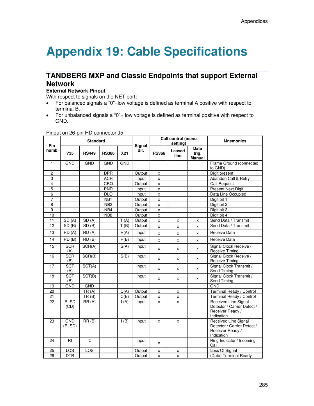
TANDBERG MXP and Classic Endpoints that support External Network
External Network Pinout
With respect to signals on the NET port:
•For balanced signals a “0”=low voltage is defined as terminal A positive with respect to terminal B.
•For unbalanced signals a “0”= low voltage is defined as terminal positive with respect to GND.
Pinout on
|
| Standard |
|
| Call control (menu | Mnemonics | |||
Pin |
|
| Signal |
| setting) |
| |||
|
|
|
|
|
|
| |||
numb |
|
|
|
| dir. |
| Leased | Data |
|
V35 | RS449 | RS366 | X21 | RS366 | trig. |
| |||
|
| line |
| ||||||
|
|
|
|
|
|
| Manual |
| |
|
|
|
|
|
|
|
|
| |
1 | GND | GND | GND | GND |
|
|
|
| Frame Ground (connected |
|
|
|
|
|
|
|
|
| to GND) |
2 |
|
| DPR |
| Output | x |
|
| Digit present |
3 |
|
| ACR |
| Input | x |
|
| Abandon Call & Retry |
4 |
|
| CRQ |
| Output | x |
|
| Call Request |
5 |
|
| PND |
| Input | x |
|
| Present Next Digit |
6 |
|
| DLO |
| Input | x |
|
| Data Line Occupied |
7 |
|
| NB1 |
| Output | x |
|
| Digit bit 1 |
8 |
|
| NB2 |
| Output | x |
|
| Digit bit 2 |
9 |
|
| NB4 |
| Output | x |
|
| Digit bit 3 |
10 |
|
| NB8 |
| Output | x |
|
| Digit bit 4 |
11 | SD (A) | SD (A) |
| T (A) | Output | x | x | x | Send Data / Transmit |
12 | SD (B) | SD (B) |
| T (B) | Output | x | x | x | Send Data / Transmit |
13 | RD (A) | RD (A) |
| R(A) | Input | x | x | x | Receive Data |
14 | RD (B) | RD (B) |
| R(B) | Input | x | x | x | Receive Data |
15 | SCR | SCR(A) |
| S(A) | Input | x | x | x | Signal Clock Receive / |
| (A) |
|
|
|
| Receive Timing | |||
|
|
|
|
|
|
|
| ||
16 | SCR | SCR(B) |
| S(B) | Input | x | x | x | Signal Clock Receive / |
| (B) |
|
|
|
| Receive Timing | |||
|
|
|
|
|
|
|
| ||
17 | SCT | SCT(A) |
|
| Input | x | x | x | Signal Clock Transmit / |
| (A) |
|
|
|
| Send Timing | |||
|
|
|
|
|
|
|
| ||
18 | SCT | SCT(B) |
|
| Input | x | x | x | Signal Clock Transmit / |
| (B) |
|
|
|
| Send Timing | |||
|
|
|
|
|
|
|
| ||
19 | GND | GND |
|
|
|
|
|
| GND |
20 |
| TR (A) |
| C(A) | Output | x | x |
| Terminal Ready / Control |
21 |
| TR (B) |
| C(B) | Output | x | x |
| Terminal Ready / Control |
22 | RLSD | RR (A) |
| I (A) | Input | x | x |
| Received Line Signal |
| (CD) |
|
|
|
|
|
|
| Detector / Carrier Detect / |
|
|
|
|
|
|
|
|
| Receiver Ready / |
|
|
|
|
|
|
|
|
| Indication |
23 | GND | RR (B) |
| I (B) | Input | x | x |
| Received Line Signal |
| (RLSD) |
|
|
|
|
|
|
| Detector / Carrier Detect / |
|
|
|
|
|
|
|
|
| Receiver Ready / |
|
|
|
|
|
|
|
|
| Indication |
24 | RI | IC |
|
| Input | x |
|
| Ring Indicator / Incoming |
|
|
|
|
|
|
|
| Call | |
|
|
|
|
|
|
|
|
| |
25 | LOS | LOS |
|
| Output | x | x |
| Loss Of Signal |
26 | DTR |
|
|
| Output | x | x |
| (Data) Terminal Ready |
285