Split Type
Contents
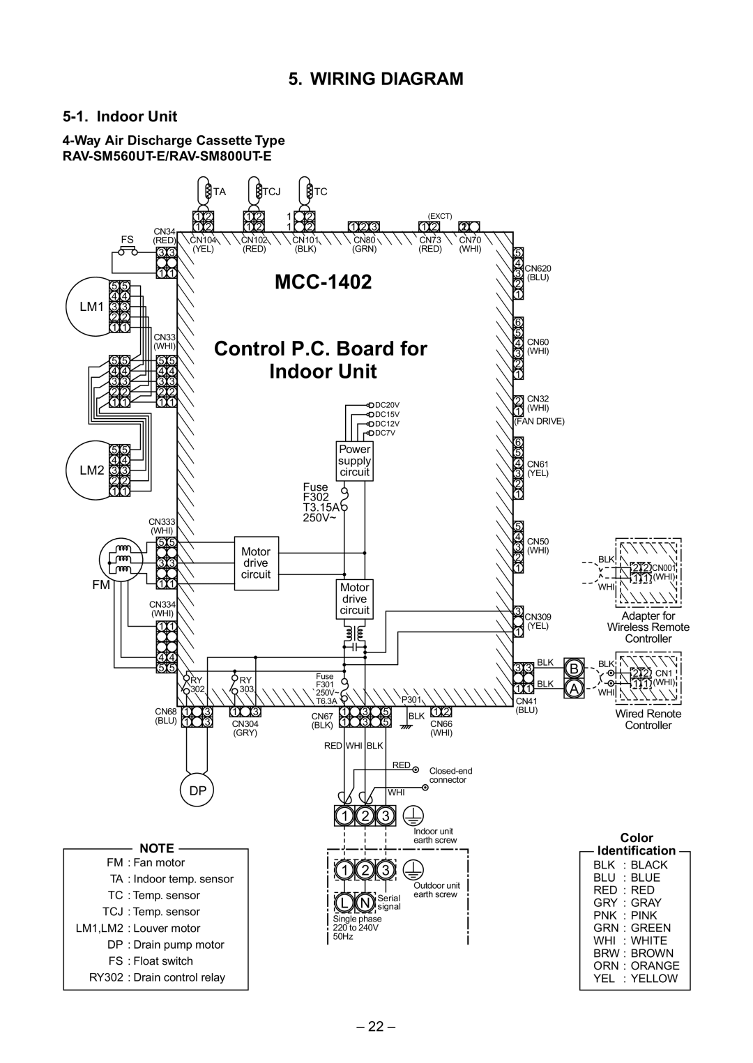
Indoor Unit
Way Air Discharge Cassette Type
Operation characteristic curve Cooling Heating
Current
Concealed Duct Type
RAV-SM560BT-E RAV-SM800BT-E
RAV-SM800BT-E
High-Wall Type
RAV-SM560KRT-E RAV-SM800KRT-E
RAV-SM800KRT-E
Flexible Type
RAV-SM560XT-E RAV-SM800XT-E
RAV-SM800XT-E
Outdoor Unit
AIR Ducting Work
Construction Views External Views
RAV-SM560BT-E
RAV-SM800BT-E
High-Wall Type RAV-SM560KRT-E/RAV-SM800KRT-E
RAV-SM560XT-E/RAV-SM800XT-E
RAV-SM560AT-E
RAV-SM800AT-E
Systematic Refrigerating Cycle Diagram
RAV-SM800UT-E, RAV-SM800BT-E, RAV-SM800KRT-E/RAV-SM800AT-E
MCC-1402
RAV-SM560BT-E/RAV-SM800BT-E
MCC-1370A
Simple Check Points for Diagnosing Faults
RAV-SM560AT-E
Board
Specifications of Electrical Parts
Accessory Separate Sold Parts
Refrigerant R410A
Processing of Piping Materials
1 Flare processing dimensions
2 Relations between flare nut and flare seal surface
Tools
Recharging of Refrigerant
Brazing of Pipes
Brazing
Indoor Control Circuit
Main Sub master remote controller
Indoor unit
Outline of specifications Remarks
Control Specifications
Remote controller Outline of control Command
Heating Auto
Operation
Operation of duct only
Standard High ceiling SM560
Control temp C
Cooling/dry operation In heating/fan operation
All modes
Frequency fixed In case of wired remote controller
Center
Last push priority
Operation Prohibited
MCC-1402
Indoor Print Circuit Board
Way Air Discharge Cassette Type RAV-SM560UT-E/RAV-SM800UT-E
MCC-1403
Concealed Duct Type
Main Sub master remote controller
Microcomputer System Block Diagram
Connection of Main Remote Controller
Indoor unit
Connection of Wireless Remote Controller
Control Specifications
Heating operation
Tc Temperature of indoor
Air volume setup SM560 SM800
Outline of specifications
Remarks
Tc C
Cool L
Figure if To 15C
Print Circuit Board
Main P.C. board MCC-1370A Sub P.C. board MCC-1370B
Pulse Modulating Valve PMV control
Discharge temperature release control
Outline of Main Controls
Current release control
Indoor P.C. Board Optional Connector Specifications
Function Connector Pin Specifications Remarks
Outdoor Controls
MCC-1398 RAV-SM560AT-E Viewed from parts of P.C board
MCC-813 RAV-SM800AT-E
MAX
Cooling operation
Outdoor fan control Object SM560
Allocations of fan tap revolutions
Heating operation
Over-current preventive control
Short intermittent operation preventive control
High-voltage suppression TE control Only for SM800
Current release value shift control
Start of heating operation
Defrost control
SM560 SM800
Wired remote controller type
Summary of Troubleshooting
Before troubleshooting
Troubleshooting procedure
Trouble
Check Code List
Error mode detected by indoor unit
Error mode detected by outdoor unit
Diagnostic function Cause of operation
Error mode detected by remote controller or network adapter
Timer Ready Wired remote Controller Check code
Check code
Error Mode Detected by LED on Outdoor P.C. Board
SW800 LED display in bit 1, bit 2, bit 3 OFF
Type a
E09 error/*99 error
Troubleshooting Procedure for Each Check Code
E01 error/*99 error
New Check Code/Present Check Code Central Control Side
E04 error/04 error
E08, L03, L07, L08 error/ *96 error 99 error
E18 error/97 error *99 error
L09 error/46 error
L30 error/B6 error
L20 error/98 error
B7 error Central controller
P10 error/Ob error
F10 error 0C error
CN333
P22 error/1A error
Single phase
P19 error/08 error
F02 error/0d error
F01 error/0F error
P26 error/14 error
P29 error/16 error
H03 error/17 error
F04 error/19 error
F06 error/18 error
F08 error/1b error
L29 error/1C error
H02 error/1d error
P03 error/1E error
H01 error/1F error
P04 error/21 error
Error Central controller
Same as others Correct connection of connector
F29 error / 12 error
E03 error Master indoor unit
P31 error Sub indoor unit
TC, TCJ sensor Caracteristics-2
TA sensor Caracteristics-1
Caracteristics-3
20 TE, TO, TS sensor
Case
Contents
R1 Readout of the setup data from Eeprom
R2 Replacement of service P.C. board
Minimum requirements for item code
R3 Writing of the setup contents to Eeprom
Type Item code
Memorandum for setup contents Item code table Example
Indoor unit capacity Item code
Test Run Setup on Remote Controller
Wired remote controller
Push SET , , and buttons concurrently for 4 seconds or more
Setup to Select Function
Procedure Use this function while the indoor unit stops
Pushing button returns the status to usual stop status
Item No. DN table Selection of function
Description At shipment
Wireless remote controller
Cabling and Setting of Remote Controller Control
Setup method
Operation
Contents
Monitor Function of Remote Controller Switch
Procedure
Requirement
Calling of error history
Group control operation
System example
LED Display Specification
Microcomputer Block Diagram
Network Address Setup Switch SW01
Network Adapter
Cable Connection
Communication Cable Specifications
Communication circuit Communication cable specifications
Network cable connection
How to set by the switch on the network adapter P.C. board
How to Set an Address Number
How to set from the remote controller at indoor unit side
Procedure Set the network address while the unit stops
101
Requirement in Service
Network address No. setup table SW01
Address No
Contents
102
Address setup procedure
Address Setup
103
Only turning on source power supply Automatic completion
Address Setup & Group Control
System configuration
Automatic address example from unset address No miscabling
Manual setting from remote controller
105
To know the position of indoor unit body by address
106
Push button if the unit stops
Push and buttons simultaneously for 4 seconds or more
Table a
RAV-SM800AT-E LED display when SW800 Bit 1, 2, 3, 4 OFF
107
Check code LED display Type D800 D801 D802 D803 Red Yellow
Troubleshooting Wall Type
108
109
Wireless remote controller type
Self-diagnosis by check code on the remote controller
Outline of Judgment
110
Self-diagnosis with remote controller
How to select remote control operation mode
111
Operating key Indication after operation
112
Self-diagnosis by check codes
Example
Check switch
Troubleshooting with Check Display of Remote Controller
Reset switch
Case of main remote controller/sub-remote controller a
Filter data
Segment display
Display on Check monitor
Check data
Reset switch
Remote controller with timer RBC-AM1E
Check switch
LCD display Standby is present
Data
116
Reset switch
Central remote controller
Check switch
117
Check Code Table
118
119
Conditioner
120
Ipdu
1A error
Troubleshooting for Each Check Code
121
Error
122
0C error
123
0F error
0d error
124
125
126
YES
127
Board CN210 Blue Yellow White Black Red
128
1C error * Except RAV-SM560AT-E
129
1F error
1d error
1E error
130
Error LCD flash
131
Indoor unit
Part name Check procedure
Simple Check Method for Main Parts
132
133
TA sensor TC, TCJ sensor Caracteristics-2 Caracteristics-1
Caracteristics-5
134
TH sensor
Detachment
No. Part name Procedure Remarks
135
Attachment
Part name Procedure Remarks
136
137
138
Fan motor 1. Detachment
139
No. Part name Procedure
Drain pan 1. Detachment
140
141
142
Replacement of Distributor Assembly
Cutting
143
RAV-SM800UT-E
Replacement of Main Parts Built-in type
144
145
Procedure
AID-P710BH, P800BH, P1120BH
Electric parts box
Supplement How to remove the electric parts box
146
Hook
147
Replacements of Main Parts Hi-Wall type
Attachment of front panel
148
149
150
Replacement Procedure of Service Main P.C. Board
Replacement Procedure
Components
Mounting
Reference Explanation about functions of switches/jumpers
151
Parts layout of service P.C. board
152
Outdoor Unit
153
154
Procedure Remarks
Part name
Requirement
155
156
157
158
159
160
161
162
Requirement
163
164
165
166
167
Product
Part Description
224
168
Location
402 404 401 405 403
169
170
222
Concealed Duct Type
403 402 406 405
171
172
RBC-U21PGW E
173
High-Wall Type
411 410 406 408 402 401 413 412 404 403
174
Inverter
175
702 TE Sensor TS Sensor To Sensor TD Sensor 701 705 703 704
176
177
DKV-MO25743BO
706
178
179
403 402 404 405 408 401 406 407
180