9-5-1. Installation Place
•A place which provides the spaces around the indoor unit as shown in the above diagram.
•A place where there is no obstacle near the air inlet and outlet.
•A place that allows easy installation of the piping to the outdoor unit.
•A place which allows the Front panel to be opened.
CAUTION
•Direct sunlight or fluorescent light to the indoor unit’s wireless receiver should be avoided.
•The microprocessor in the indoor unit should not be too close to RF noise sources.
(For details, see the owner’s manual.)
<Remote controller>
•A place where there are no obstacles such as a curtain that may block the signal from the indoor unit.
•Do not install the remote controller in a place exposed to direct sunlight or close to a heating source, such as a stove.
•Keep the remote controller at least 1 m apart from the nearest TV set or stereo equipment. (This is necessary to prevent image disturbances or noise interference.)
•The location of the remote controller should be determined as shown below.
<Remote controller usage>
•Under Ceiling Installation
Ceiling
7 | m |
|
|
|
|
|
|
|
|
| |
Wall |
|
|
|
|
|
|
|
| m | m |
|
Remote controller |
|
| 5 | m | |
5 |
|
| |||
Reception range |
|
|
| *7 | |
|
|
|
| ||
| Reception | Remote |
| ||
| range |
|
| controller | |
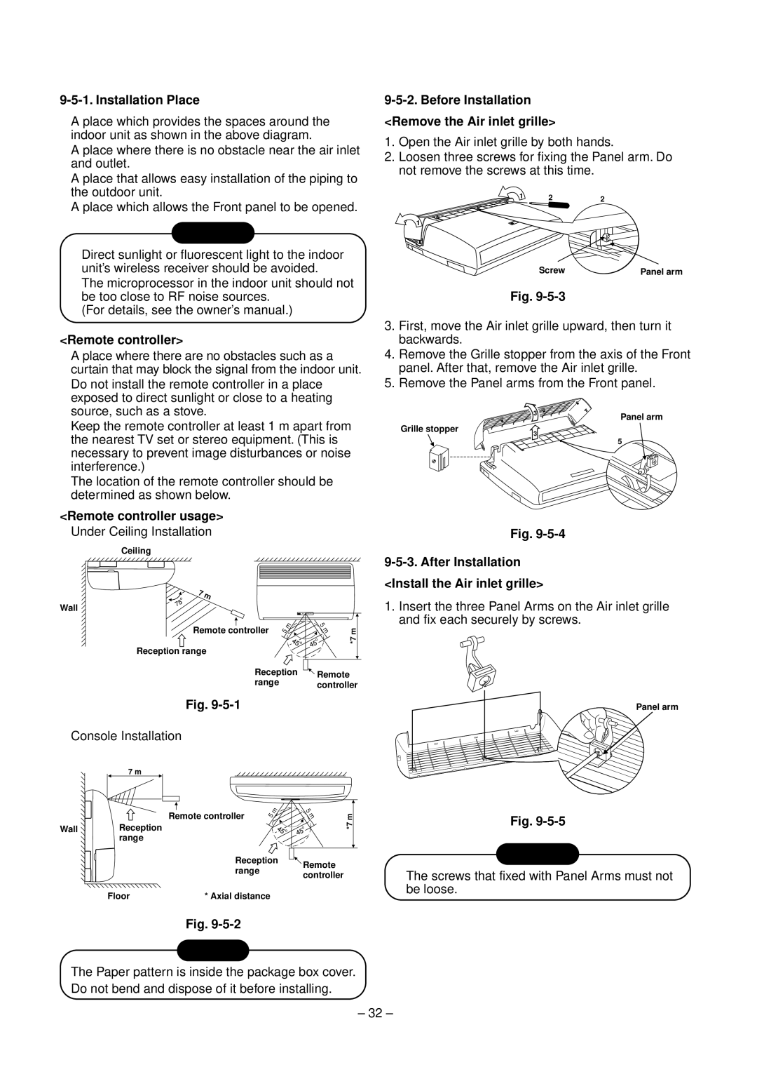
9-5-2. Before Installation
<Remove the Air inlet grille>
1.Open the Air inlet grille by both hands.
2.Loosen three screws for fixing the Panel arm. Do not remove the screws at this time.
1 | 2 | 2 |
1
Screw | Panel arm |
Fig.
3.First, move the Air inlet grille upward, then turn it backwards.
4.Remove the Grille stopper from the axis of the Front panel. After that, remove the Air inlet grille.
5.Remove the Panel arms from the Front panel.
| 3 | Panel arm |
|
| |
Grille stopper | 3 |
|
| 5 | |
|
|
Fig.
9-5-3. After Installation <Install the Air inlet grille>
1.Insert the three Panel Arms on the Air inlet grille and fix each securely by screws.
Fig.
•Console Installation
7 m
Remote controller | 5 | m |
|
WallReception range
Reception range
5 m m *7
Remote controller
Panel arm
Fig.
CAUTION
• The screws that fixed with Panel Arms must not |
be loose. |
Floor | * Axial distance |
Fig.
NOTICE
The Paper pattern is inside the package box cover. Do not bend and dispose of it before installing.
– 32 –