No. Part name | Procedure | Remarks | |
|
|
| |
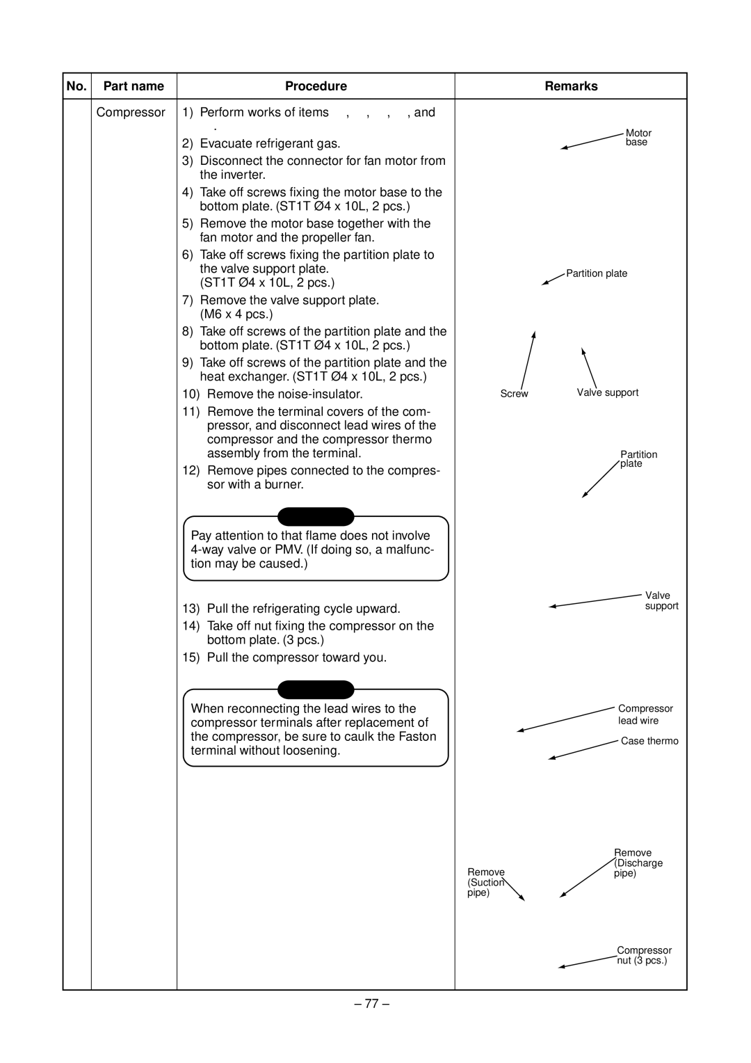
† Compressor 1) | Perform works of items •, ‚, ƒ, „, and |
| |
| …. | Motor | |
2) | Evacuate refrigerant gas. | ||
base |
3)Disconnect the connector for fan motor from the inverter.
4)Take off screws fixing the motor base to the bottom plate. (ST1T Ø4 x 10L, 2 pcs.)
5)Remove the motor base together with the fan motor and the propeller fan.
6)Take off screws fixing the partition plate to
the valve support plate. | Partition plate | |
(ST1T Ø4 x 10L, 2 pcs.) | ||
|
7)Remove the valve support plate. (M6 x 4 pcs.)
8) Take off screws of the partition plate and the bottom plate. (ST1T Ø4 x 10L, 2 pcs.)
9)Take off screws of the partition plate and the heat exchanger. (ST1T Ø4 x 10L, 2 pcs.)
10) Remove the | Screw | Valve support |
11)Remove the terminal covers of the com- pressor, and disconnect lead wires of the compressor and the compressor thermo
assembly from the terminal. | Partition |
12) Remove pipes connected to the compres- | plate |
| |
sor with a burner. |
|
CAUTION
Pay attention to that flame does not involve
| Valve |
13) Pull the refrigerating cycle upward. | support |
14)Take off nut fixing the compressor on the bottom plate. (3 pcs.)
15)Pull the compressor toward you.
CAUTION |
| |
When reconnecting the lead wires to the | Compressor | |
compressor terminals after replacement of | lead wire | |
the compressor, be sure to caulk the Faston | Case thermo | |
terminal without loosening. | ||
|
Remove (Discharge
Removepipe) (Suction
pipe)
Compressor
![]() nut (3 pcs.)
nut (3 pcs.)
– 77 –
