In addition to the code checking by remote controller of the indoor unit, troubles of the outdoor unit can be diagnosed by LED indications on the cycle control P.C. board of the outdoor unit. Utilize them for various checks.
For the check by remote controller of the indoor unit, refer to the installation Manual of the indoor unit. Before a check, confirm each bit of the DIP switch is set to OFF position.
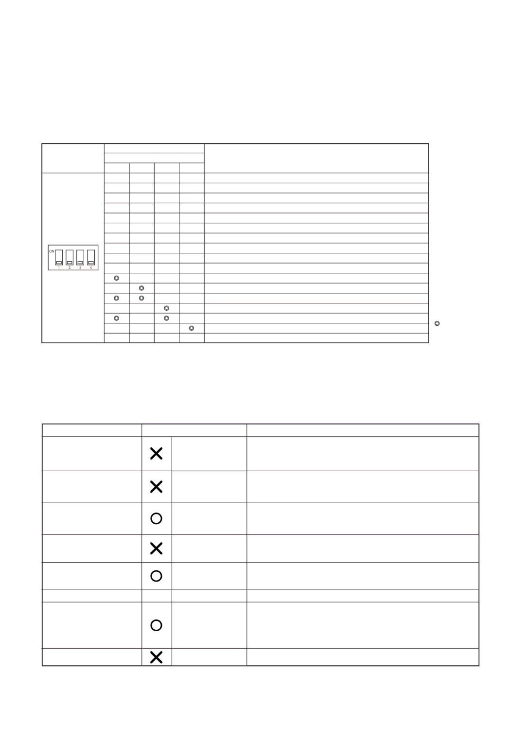
LED indication and code checking
|
| DIP switch |
|
|
| Cycle control P.C. board |
| |||||||||
|
|
|
|
|
|
|
|
|
| |||||||
|
|
|
| LED indication |
| Cause | ||||||||||
|
|
| SW800 |
|
|
|
|
| ||||||||
|
|
|
|
|
|
|
|
|
|
| ||||||
|
|
|
|
|
|
|
|
|
|
|
| D800 | D801 | D802 | D803 |
|
|
|
|
|
|
|
|
|
|
|
|
| \ | [ | [ | [ | Heat exchanger sensor (TE) error |
|
|
|
|
|
|
|
|
|
|
|
|
|
|
|
|
|
|
|
|
|
|
|
|
|
|
|
|
| [ | [ | \ | [ | Suction sensor (TS) error |
|
|
|
|
|
|
|
|
|
|
|
|
|
|
|
|
|
|
|
|
|
|
|
|
|
|
|
|
| \ | \ | [ | [ | Discharge sensor (TD) error |
|
|
|
|
|
|
|
|
|
|
|
|
|
|
|
|
|
|
|
|
|
|
|
|
|
|
|
|
| [ | \ | [ | \ | |
|
|
|
|
|
|
|
|
|
|
|
|
|
|
|
|
|
|
|
|
|
|
|
|
|
|
|
|
| [ | \ | [ | [ | Outdoor temperature sensor (TO) error |
|
|
|
|
|
|
|
|
|
|
|
|
|
|
|
|
|
|
|
|
|
|
|
|
|
|
|
|
| \ | \ | \ | [ | DC outside fan error |
|
|
|
|
|
|
|
|
|
|
|
|
|
|
|
|
|
|
|
|
|
|
|
|
|
|
|
|
| \ | [ | [ | \ | Communication error between IPDU |
|
|
|
|
|
|
|
|
|
|
|
| [ | \ | \ | [ | Discharge temp. error |
| ON |
|
|
|
|
|
|
|
|
|
| |||||
|
|
|
|
|
|
|
|
|
|
|
| \ | \ | [ | \ | EEPROM error |
|
|
|
|
|
|
|
|
|
|
|
|
|
|
|
|
|
|
|
|
|
|
|
|
|
|
|
|
| [ | [ | \ | \ | Communication error between IPDU |
| 1 | 2 | 3 |
|
| 4 |
|
| ||||||||
|
|
|
|
|
|
|
|
|
|
|
|
|
|
|
|
|
|
|
|
|
|
|
|
|
|
|
|
|
| [ | [ | [ | |
|
|
|
|
|
|
|
|
|
|
|
|
|
|
|
|
|
|
|
|
|
|
|
|
|
|
|
|
| [ |
| [ | [ | Detect circuit error |
|
|
|
|
|
|
|
|
|
|
|
|
|
|
|
|
|
|
|
|
|
|
|
|
|
|
|
|
|
|
| [ | [ | Current sensor error |
|
|
|
|
|
|
|
|
|
|
|
|
|
|
|
|
|
|
|
|
|
|
|
|
|
|
|
|
| [ | [ |
| [ | Comp. lock error |
|
|
|
|
|
|
|
|
|
|
|
|
|
|
|
|
|
|
|
|
|
|
|
|
|
|
|
|
|
| [ |
| [ | Comp. break down |
|
|
|
|
|
|
|
|
|
|
|
|
|
|
|
|
|
|
|
|
|
|
|
|
|
|
|
|
| [ | [ | [ |
| Phase missing detection, Detection of |
|
|
|
|
|
|
|
|
|
|
|
|
|
|
|
|
|
|
|
|
|
|
|
|
|
|
|
|
| [ | \ | [ | \ | Serial communication error by thermo. operation of Comp. case |
LED
indication
D800 : Red
\
D801 : Yellow
\
D802 : Yellow
\
D803 : Yellow
\
: Rapid flash
[: Go off \ : Go on
In the case of an air conditioner using R410A, in order to prevent any other refrigerant from being charged accidentally, the service port diameter of the outdoor unit control valve (3 way valve) has been changed. (1/2 UNF 20 threads per inch)
•In order to increase the pressure resisting strength of the refrigerant piping, flare processing diameter and size of opposite side of flare nuts has been changed. (for copper pipes with nominal dimensions 1/2 and 5/8)
New tools for R410A
New tools for R410A | Applicable to R22 model | Changes | |
|
|
|
|
Gauge manifold |
|
| As pressure is high, it is impossible to measure by means of conventional gauge. |
|
|
| In order to prevent any other refrigerant from being charged, each port diameter is |
|
|
| changed. |
|
|
|
|
Charge hose |
|
| In order to increase pressure resisting strength, hose materials and port size are |
|
|
| changed (to 1/2 UNF 20 threads per inch). |
|
|
| When purchasing a charge hose, be sure to check the port size. |
|
|
|
|
Electronic balance |
|
| As pressure is hight and gasification speed is fast, it is difficult to read the |
for refrigerant charging |
|
| indicated value by means of charging cylinder, as air bubbles occur. |
|
|
|
|
Torque wrench |
|
| The size of opposite sides of flare nuts have been increased. Incidentally, a |
(nominal diam. 1/2, 5/8) |
|
| common wrench is used for nominal diameters 1/4 and 3/8. |
|
|
|
|
Flare tool |
|
| By increasing the clamp bar’s receiving hole, strength of spring in the tool has |
(clutch type) |
|
| been improved. |
|
|
|
|
Gauge for projection adjustment | — | — | Used when flare is made with using conventional flare tool. |
|
|
|
|
Vacuum pump adapter |
|
| Connected to the conventional vacuum pump. It is necessary to use an adapter to |
|
|
| prevent vacuum pump oil from flowing back to the charge hose. |
|
|
| The charge hose connecting part has two |
|
|
| (7/16 UNF 20 threads per inch) and one for R410A. If the vacuum pump oil |
|
|
| (mineral) mixes with R410A a sludge may occur and damage the equipment. |
Gas leakage detector
Exclusive for HFC refrigerant.
•Incidentally, the “refrigerant cylinder” comes with the refrigerant designation (R410A) and protector coating in the U. S’s ARI specified rose color (ARI color code: PMS 507).
•Also, the “charge port and packing for refrigerant cylinder” require 1/2 UNF 20 threads per inch corresponding to the charge hose’s port size.
– 44 –