AIR-CONDITIONER
Contents
Indoor Unit
Specifications
Current
Operation characteristic curve Cooling Heating
RAV-SM560AT-E RAV-SM800AT-E
Outdoor Unit
Construction Views
Outdoor Unit RAV-SM560AT-E
Outdoor Unit RAV-SM800AT-E
RAV-SM560XT-E / RAV-SM560AT-E
Systematic Refrigerating Cycle Diagram
Indoor unit
RAV-SM800XT-E / RAV-SM800AT-E
Color Identification
Wiring Diagram
L N
Board
Parts name Type Specifications
Specification of Electrical Parts
Piping materials and joints used
Safety During Installation/Servicing
Refrigerant Piping Installation
Refrigerant R410A
1 Thicknesses of annealed copper pipes Thickness mm
Outer diameter mm R410A R22
Processing of piping materials
Width
Clutch type Wing nut type
·m kgf·m
·m kgf·cm
Tools
Required tools
General tools Conventional tools can be used
Recharging of Refrigerant
1 Configuration of refrigerant charging
Brazing of Pipes
Filler Flux
Characteristics required for flux
Types of flux Noncorrosive flux
Activated flux
Operation
Control Block Diagram
Operation Description
When power supply is reset
Operation mode selection
Air volume control
1 Cold draft preventing control
Cool air discharge preventive control
Filter sign display
Freeze preventive control Low temperature release
High-temp release control
Louver control
Motions
How to set auto restart function
Auto Restart Function
Operation
Filter Check Lamp
How to cancel auto restart function
Power failure during timer operation
How to turn off filter check lamp
Console Installation
Installation Procedure
Installation Diagram of Indoor and Outdoor Units
Under Ceiling Installation
To Disconnect the Appliance from Main Power Supply
Precautions for Safety
Page
Accessory parts and Parts to be procured locally
Accessory parts
Parts to be procured locally
Avoid installing in the following places
Selection of Installation Place
Before Installation Remove the Air inlet grille
Installation Place
Remote controller
Remote controller usage
Piping and Drain Hose Installation
Install the indoor unit
Install the Suspension bolts
Condition for Installation
Connect the Flexible pipe 5 to the large pipe Gas side
Cutting a hole and mounting the Installation plate
Unit must not decline more than 15 mm in either
Axis
Drainage
Drain Piping Work
Refrigerant Piping
Tightening connection
Evacuating
Heat insulation
For RAV-SM560AT-E model
Electrical Work
Final Installation Checks
LED indication and code checking
Environment
Troubleshooting procedure
Troubleshooting
Summary of Troubleshooting
Before troubleshooting
How to use remote control in service mode
Self-Diagnosis by Remote Control Check Code
Judgement and action
No display in the setting at shipment
Operation
YES
Troubleshooting for Each Check Code 1A error
Error
1C error* Except RAV-SM560AT-E
1D error
1E error
1F error
Connector normal?
TD sensor Caracteristics-4
TA sensor TC, TCJ sensor Caracteristics-1 Caracteristics-2
Caracteristics-3
20 TE, TO, TS sensor
Inspection procedure
Compressor does not operate
Primary check
Cooling and heating model
Are all of compressor cords normal?
How to install the Air inlet grille
Detachments
Remove the Panel arms from the Front panel
Open 3 Cap screws and remove the screws
How to remove the Drain pan
Refrigeration How to remove the Refrigeration assembly
Assembly Pan assembly
Part name Procedures Remarks
How to remove the Multiblade fan
Fan motor
Detachment
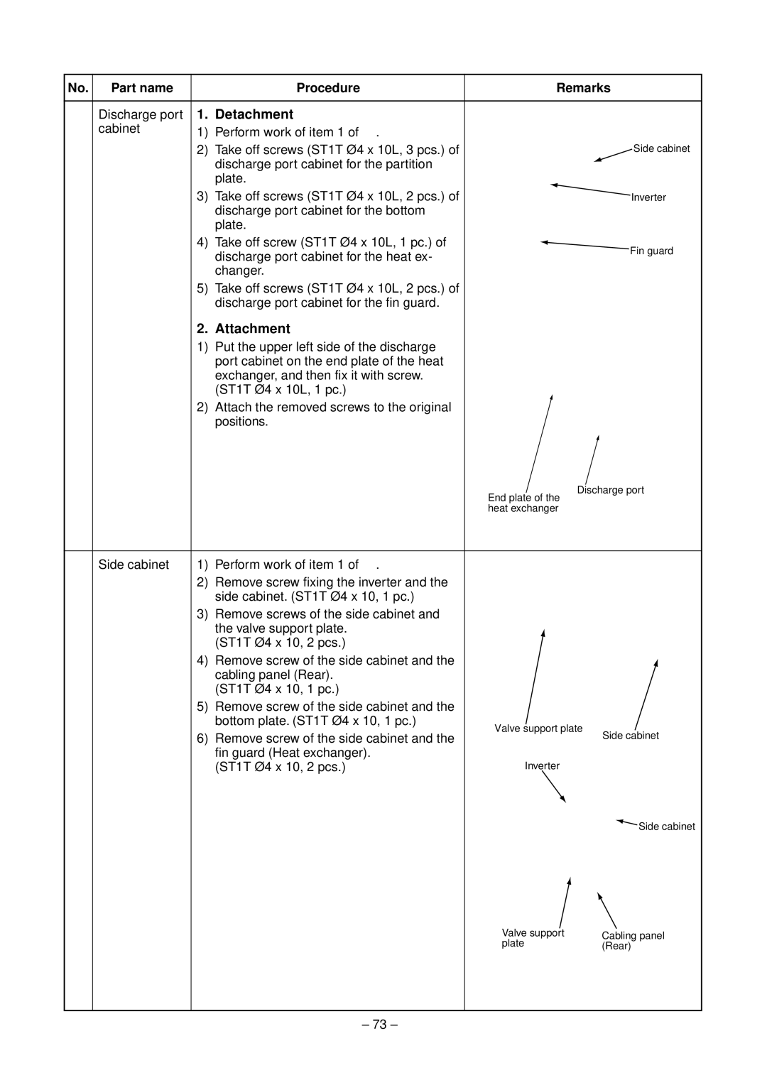
No. Part name Procedure Remarks
Procedure Remarks
Requirement
Connection with the power terminal
Part name Procedure Remarks
‡ Compressor Perform works of items 1 ‚, ƒ, „, …
Fan guard
Remove the upper cabinet
Discharge port cabinet for the heat ex
Part name
Requirement
… Control P.C Remove the inverter box from P.C. board base
Loosen the flange nut by turning clock
† Compressor Perform works of items , ‚, ƒ, „,
Ø4 x 10L , 2 pcs. per one reactor
Product
Indoor Unit E-Parts Assy
Exploded Views and Parts List
Air Inlet Grille
Inverter
21,22 16,17
702 TE Sensor TS Sensor To Sensor TD Sensor 701 705 703 704
Outdoor Unit Inverter Assy, RAV-SM560AT-E
Outdoor Unit Inverter Assy, RAV-SM800AT-E
Inverter BOX