May
Page
Chiller System Design and Control
Preface
Contents
100
Chiller
Primary System Components
Chiller evaporator
Primary System Components
Effect of chilled-water flow rate and variation
Effect of chilled-water temperature
Water-cooled condenser
Effect of condenser-water temperature
Effect of condenser-water flow rate
Packaged or Split System?
Maintenance
Air-cooled condenser
Air-cooled versus water-cooled condensers
Energy efficiency
Low-ambient operation
Air-cooled or water-cooled efficiency
Loads
Two-way valve load control
Three-way valve load control
Face-and-bypass dampers
Variable-speed pump load control
Chilled-water pump
Chilled-Water Distribution System
Pump per chiller
Distribution piping
Manifolded pumps
Constant flow system
Pumping arrangements
Variable-primary system
Condenser-Water System
Cooling tower
Primary-secondary system
Single tower per chiller
Condenser-water pumping arrangements
Effect of load on cooling tower performance
Effect of ambient conditions on cooling tower performance
Chiller control
Unit-Level Controls
Recommended chiller-monitoring points per Ashrae Standard
Centrifugal chiller with AFD
Centrifugal chiller capacity control
AFD on both chillers
Small Chilled-Water Systems 1-2 chillers
Application Considerations
Variable flow
Application Considerations Constant flow
Condensing method
Part load system operation
Application Considerations
Number of chillers
Parallel or series
Managing control complexity
Mid-Sized Chilled-Water Systems Chillers
Preferential vs. equalized loading and run-time
Large Chilled-Water Systems + Chillers, District Cooling
Large chilled-water system schematic
Pipe size
Power
Water
Controls
Chiller performance testing
Limitations of field performance testing
Chiller Plant System Performance
SYS-APM001-EN
SYS-APM001-EN
Guidance for Chilled- and Condenser-Water Flow Rates
System Design Options
Standard rating temperatures
Chilled-Water Temperatures
System Design Options
Chilled- and Condenser-Water Flow Rates
Condenser-Water Temperatures
Standard rating flow conditions
System Design Options Selecting flow rates
Low-flow conditions for cooling tower Base Case Low Flow
DP2/DP1 = Flow2/Flow11.85
System summary at full load
Total system power Component Power kW Base Case Low Flow
Chilled water system performance at part load
Coil response to decreased entering water temperature
System design
Entering fluid temperature, F C
Cooling-tower options with low flow
Smaller tower
Same tower, smaller approach
ΔT2 = 99.1 78 = 21.1F or 37.3 25.6 = 11.7C
Same tower, smaller approach Present Smaller Approach
Same tower, larger chiller
Retrofit capacity changes Larger Present Chiller Same tower
Retrofit opportunities
Cost Implications
Misconception 1-Low flow is only good for long piping runs
Misconceptions about Low-Flow Rates
KWh
SYS-APM001-EN
Parallel Chillers
System Configurations
Parallel chillers with separate, dedicated chiller pumps
System Configurations
Series chillers
Series Chillers
Hydraulic decoupling
Primary-Secondary Decoupled Systems
Check valves
Production loop
System Configurations Production
Distribution-loop benefits of decoupled system arrangement
System Configurations Distribution
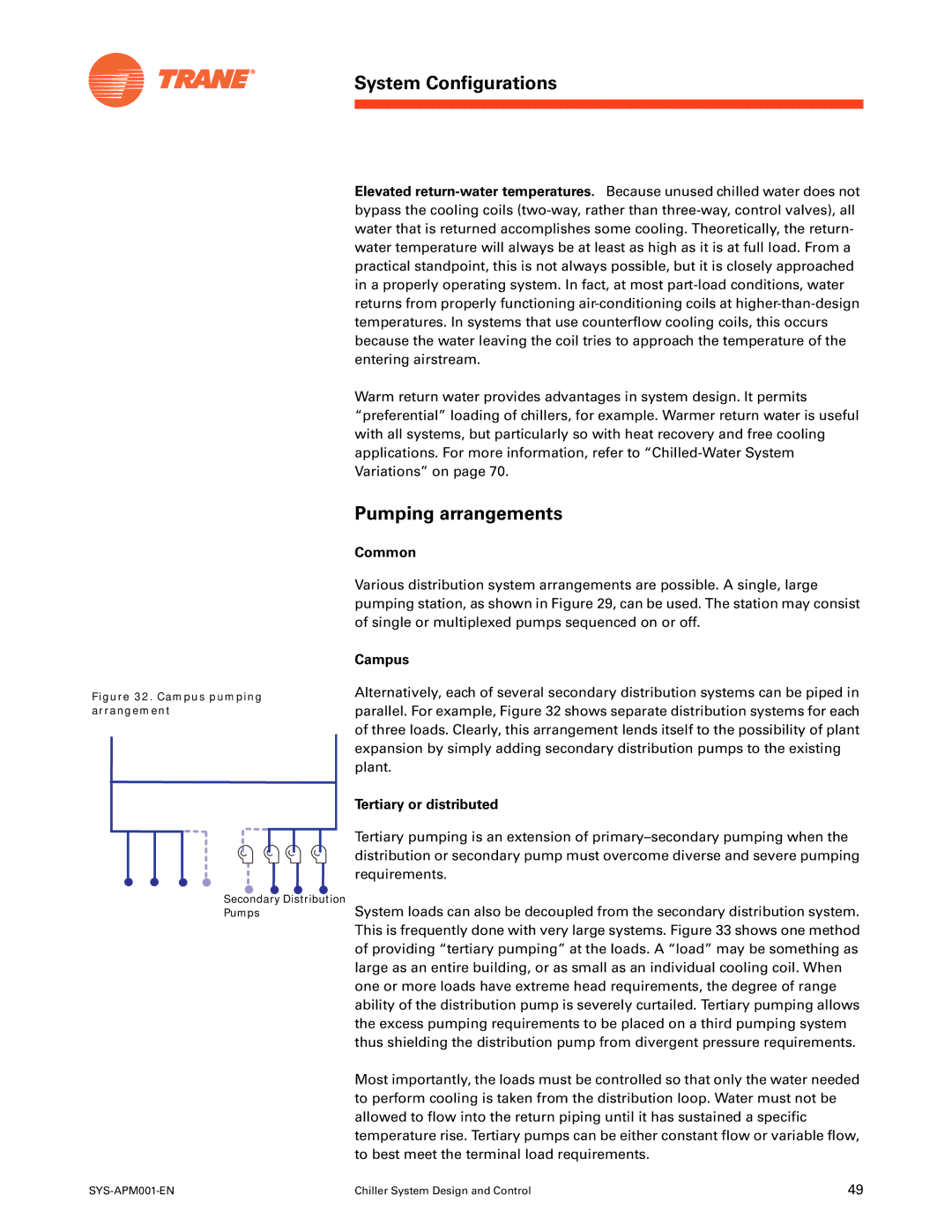
Campus
Common
Tertiary or distributed
Tertiary pumping arrangement
Decoupled system-principle of operation
Flow-based control
Temperature-sensing
Flow-sensing
Adding a chiller
Multiple chilled-water plants on a distribution loop
Subtracting a chiller
Double-ended decoupled system
Pump control in a double-ended decoupled system
Chiller sequencing in a double-ended decoupled system
Other plant designs
Variable-Primary-Flow Systems
Operational savings of VPF designs
Advantages of variable primary flow
Dispelling a common misconception
Chiller selection requirements
Flow, ft.water Flow rate
Flow-rate changes that result from isolation-valve operation
Managing transient water flows
System Configurations
Effect of dissimilar evaporator pressure drops
System design and control requirements
Accurate flow measurement
Bypass flow control
Chiller sequencing in VPF systems
Flow-rate-fluctuation examples
Adding a chiller in a VPF system
Sequencing based on load
Subtracting a chiller in a VPF system
Select slow-acting valves to control the airside coils
Other VPF control considerations
Consider a series arrangement for small VPF applications
Plant configuration
Chiller selection
Guidelines for a successful VPF system
Airside control
Plant configuration
Bypass flow
Chiller sequencing
Plate-and-frame heat exchanger
Heat Recovery
Chilled-Water System Variations
Condenser Free Cooling or Water Economizer
Refrigerant migration
Chilled-Water System Variations
Well, river, or lake water
Refrigerant migration chiller in free-cooling mode
Preferential loading parallel arrangement
Preferential Loading
Sidestream plate-and-frame heat exchanger
Preferential loading sidestream arrangement
Chilled-Water System Variations
Sidestream with alternative fuels or absorption
Sidestream system control
Preferential loading series arrangement
Series-series counterflow
Series-Counterflow Application
Evaporators
Unequal Chiller Sizing
Condensers
Low ΔT Syndrome
System Issues and Challenges
Amount of Fluid in the Loop
Example
System Issues and Challenges
Chiller response to changing conditions
System response to changing conditions
Minimum capacity required
Contingency
Type and size of chiller
Ancillary equipment
System Issues and Challenges Location of equipment
Alternative Energy Sources
Water and electrical connections
Alternative fuel
Plant Expansion
Thermal storage
Applications Outside the Chiller’s Range
Retrofit Opportunities
Flow rate out of range
Precise temperature control
System Issues and Challenges Temperatures out of range
Precise temperature control, multiple chillers
Chilled-water pump control
Chilled water reset-raising and lowering
System Controls
Chilled-Water System Control
System Controls
Critical valve reset pump pressure optimization
Number of chillers to operate
Chillers Difference
Condenser-Water System Control
Minimum refrigerant pressure differential
VFDs and centrifugal chillers performance at 90% load
Cooling-tower-fan control
Condenser-water temperature control
Chiller-tower energy consumption
Chiller-tower energy balance
Chiller-tower-pump balance
System Controls Variable condenser water flow
Effect of chiller load on water pumps and cooling tower fans
Decoupled condenser-water system
CDWP-2
Failure recovery
Failure Recovery
Conclusion
Glossary
Pumps system
Glossary
Glossary
Plant. Idea 88th Annual Conference Proceedings 1997
References
Engineering July
References
102
Ashrae
Index
Index
105
106
Page
Trane