46 TROUBLESHOOTING
Troubleshooting:
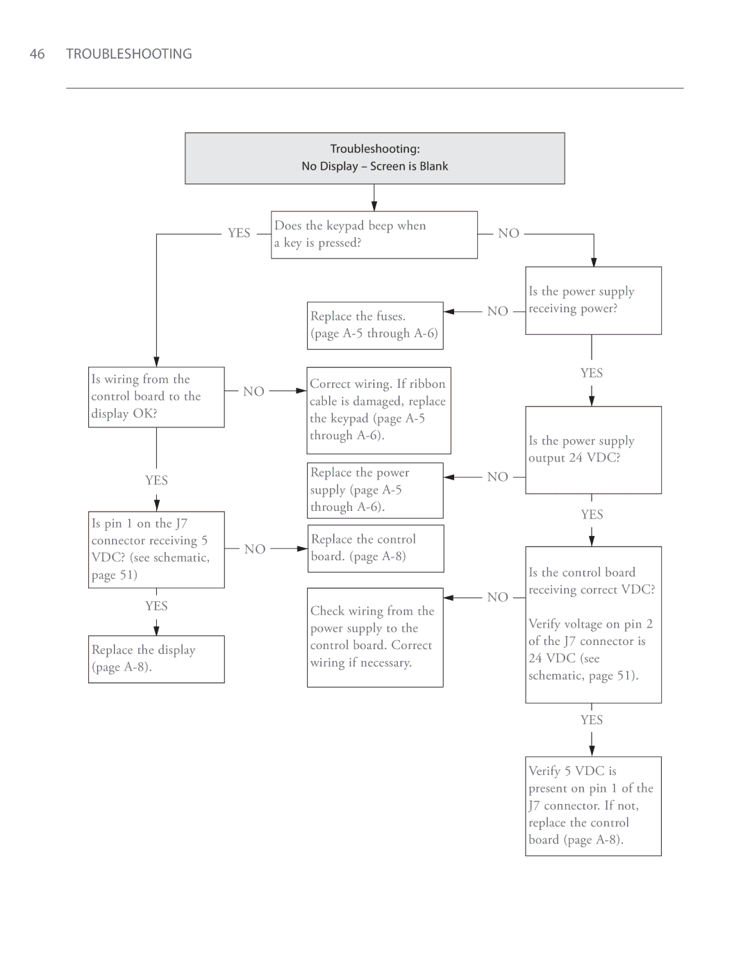
No Display – Screen is Blank
|
|
|
|
|
|
| Does the keypad beep when |
| |
YES |
|
| ||
| a key is pressed? |
| ||
|
|
| ||
|
|
|
|
|
NO
Is wiring from the control board to the display OK?
YES
NO
Replace the fuses. ![]() (page
(page
Correct wiring. If ribbon cable is damaged, replace the keypad (page
Replace the power supply (page
NO
NO
Is the power supply receiving power?
YES
Is the power supply output 24 VDC?
YES
Is pin 1 on the J7 connector receiving 5 VDC? (see schematic, page 51)
YES
Replace the display (page
NO | Replace the control | |
board. (page | ||
|
Check wiring from the power supply to the control board. Correct wiring if necessary.
NO
Is the control board receiving correct VDC?
Verify voltage on pin 2 of the J7 connector is 24 VDC (see schematic, page 51).
YES
Verify 5 VDC is present on pin 1 of the J7 connector. If not, replace the control board (page