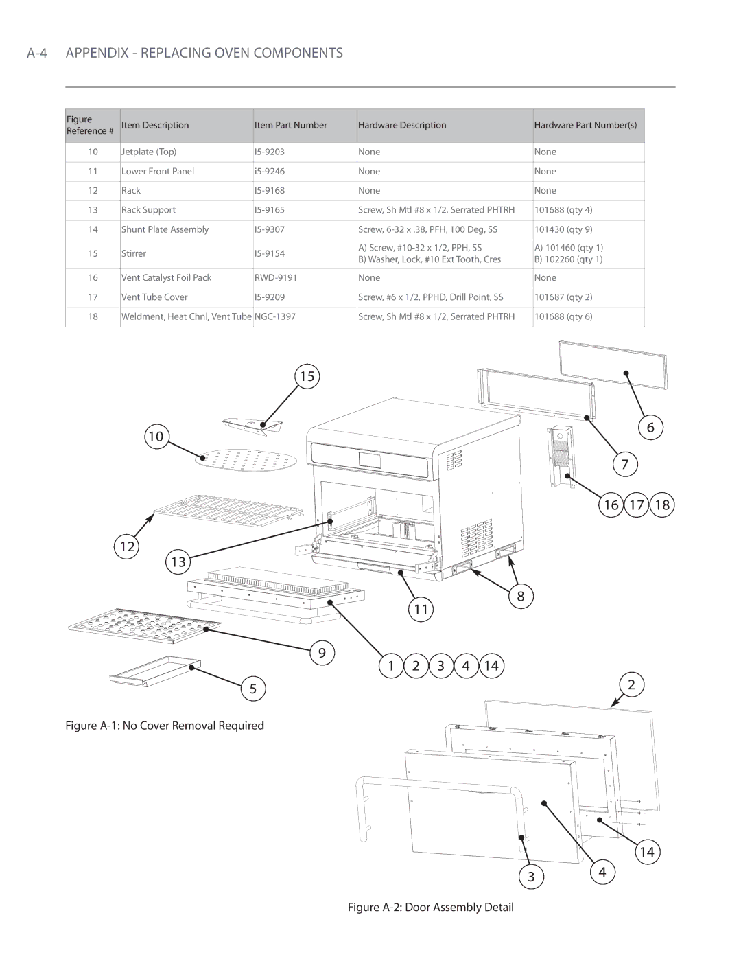
Figure | Item Description | Item Part Number | Hardware Description | Hardware Part Number(s) | |
Reference # | |||||
|
|
|
|
| |
10 | Jetplate (Top) | None | None | ||
|
|
|
|
| |
11 | Lower Front Panel | None | None | ||
|
|
|
|
| |
12 | Rack | None | None | ||
|
|
|
|
| |
13 | Rack Support | Screw, Sh Mtl #8 x 1/2, Serrated PHTRH | 101688 (qty 4) | ||
|
|
|
|
| |
14 | Shunt Plate Assembly | Screw, | 101430 (qty 9) | ||
|
|
|
|
| |
15 | Stirrer | A) Screw, | A) 101460 (qty 1) | ||
B) Washer, Lock, #10 Ext Tooth, Cres | B) 102260 (qty 1) | ||||
|
|
| |||
|
|
|
|
| |
16 | Vent Catalyst Foil Pack | None | None | ||
|
|
|
|
| |
17 | Vent Tube Cover | Screw, #6 x 1/2, PPHD, Drill Point, SS | 101687 (qty 2) | ||
|
|
|
|
| |
18 | Weldment, Heat Chnl, Vent Tube | Screw, Sh Mtl #8 x 1/2, Serrated PHTRH | 101688 (qty 6) | ||
|
|
|
|
|
15
10
6
7
16 17 18
12
13
8
11
9 | 2 | 3 | 4 | 14 |
1 |
5 | 2 |
|
Figure A-1: No Cover Removal Required
14
3 4
