Installing Standalone Units
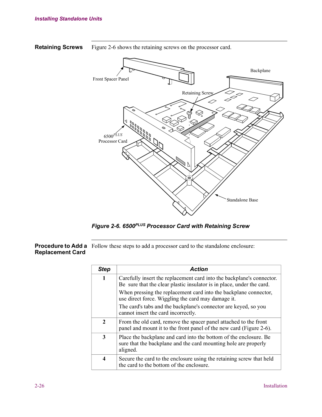
Retaining Screws Figure
Backplane
Front Spacer Panel
Retaining Screw
6500PLUS
Processor Card
Standalone Base
Figure 2-6. 6500PLUS Processor Card with Retaining Screw
Procedure to Add a Follow these steps to add a processor card to the standalone enclosure:
Replacement Card
Step | Action |
|
|
1 | Carefully insert the replacement card into the backplane's connector. |
| Be sure that the clear plastic insulator is in place, under the card. |
| When pressing the replacement card into the backplane connector, |
| use direct force. Wiggling the card may damage it. |
| The card's tabs and the backplane's connector are keyed, so you |
| cannot insert the card incorrectly. |
|
|
2 | From the old card, remove the spacer panel attached to the front |
| panel and mount it to the front panel of the new card (Figure |
|
|
3 | Place the backplane and card into the bottom of the enclosure. Be |
| sure that the backplane and the card mounting hole are properly |
| aligned. |
|
|
4 | Secure the card to the enclosure using the retaining screw that held |
| the card to the bottom of the enclosure. |
|
|
Installation |
