Hardware
Processor Card Figure
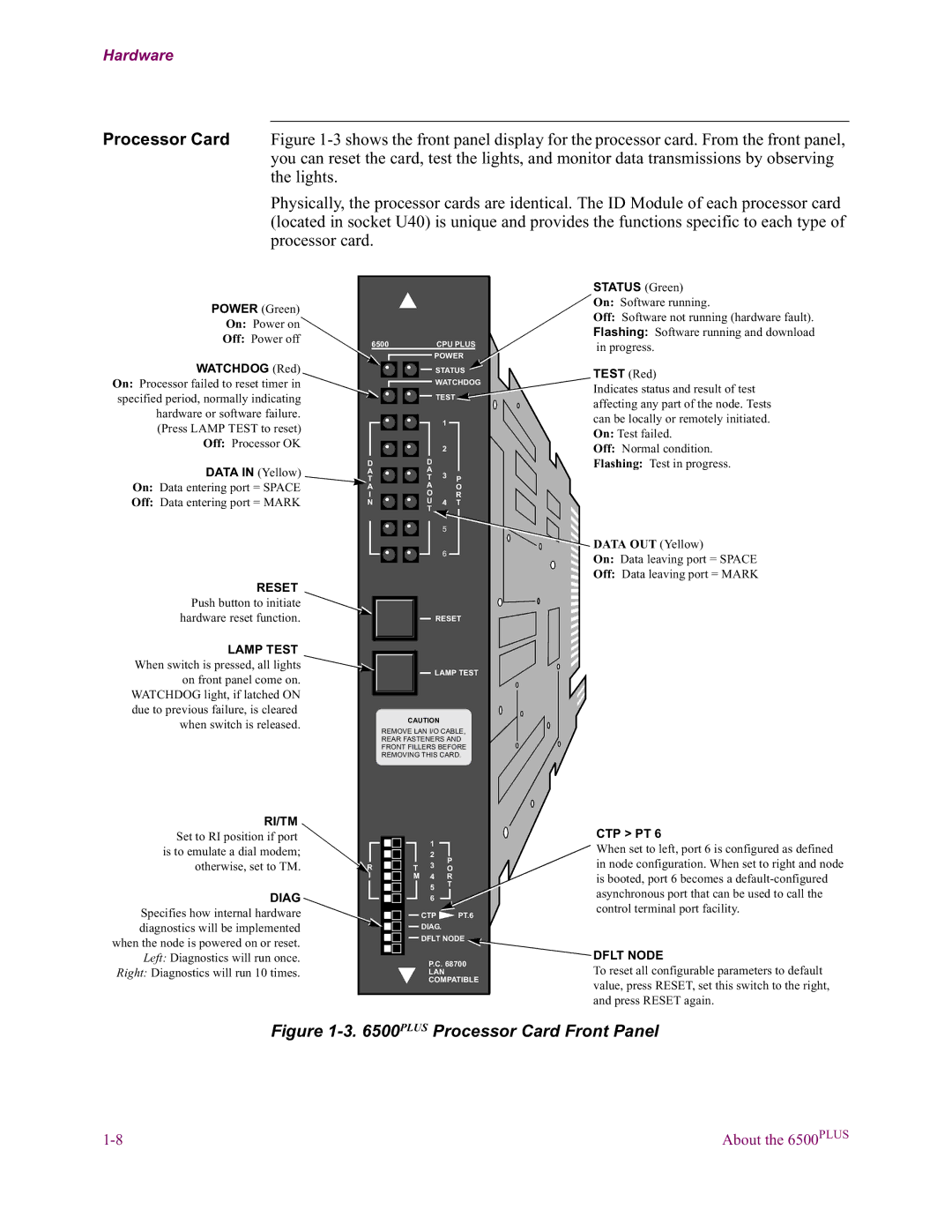
Physically, the processor cards are identical. The ID Module of each processor card (located in socket U40) is unique and provides the functions specific to each type of processor card.
POWER (Green) |
|
|
|
|
|
|
|
|
|
On: Power on |
|
|
|
|
|
|
|
|
|
Off: Power off | 6500 |
|
|
|
|
| CPU PLUS | ||
|
|
|
|
|
| ||||
WATCHDOG (Red) |
|
|
|
|
|
|
| POWER | |
|
|
|
|
|
|
| |||
|
|
|
|
|
|
| STATUS | ||
On: Processor failed to reset timer in |
|
|
|
|
|
|
| WATCHDOG | |
specified period, normally indicating |
|
|
|
|
|
|
| TEST | |
hardware or software failure. |
|
|
|
|
|
|
| 1 |
|
|
|
|
|
|
|
|
| ||
(Press LAMP TEST to reset) |
|
|
|
|
|
|
|
| |
|
|
|
|
|
|
|
|
| |
Off: Processor OK |
|
|
|
|
|
|
| 2 |
|
|
|
|
|
|
|
|
| ||
|
|
|
|
|
|
|
|
| |
DATA IN (Yellow) | D |
|
|
| D |
|
| ||
A |
|
|
|
| A | 3 |
| ||
|
|
|
| T | P | ||||
On: Data entering port = SPACE | T |
|
|
|
| ||||
A |
|
|
| A |
| O | |||
|
|
| O |
| |||||
Off: Data entering port = MARK | I |
|
|
|
|
| R | ||
N |
|
|
|
| U | 4 | T | ||
|
|
|
|
|
|
| T | 5 |
|
|
|
|
|
|
|
|
|
| |
|
|
|
|
|
|
|
|
| |
|
|
|
|
|
|
|
| 6 |
|
|
|
|
|
|
|
|
|
| |
RESET |
|
|
|
|
|
|
|
|
|
Push button to initiate |
|
|
|
|
|
|
|
|
|
|
|
|
|
|
|
|
|
| |
hardware reset function. |
|
|
|
|
|
|
| RESET | |
LAMP TEST |
|
|
|
|
|
|
|
|
|
|
|
|
|
|
|
|
|
| |
When switch is pressed, all lights |
|
|
|
|
|
|
| LAMP TEST | |
on front panel come on. |
|
|
|
|
|
|
| ||
|
|
|
|
|
|
|
|
| |
WATCHDOG light, if latched ON |
|
|
|
|
|
|
|
|
|
|
|
|
|
|
|
|
|
| |
due to previous failure, is cleared |
|
|
|
|
|
|
|
|
|
when switch is released. |
|
|
|
| CAUTION |
| |||
|
| REMOVE LAN I/O CABLE, | |||||||
|
|
| |||||||
|
|
| REAR FASTENERS AND | ||||||
|
|
| FRONT FILLERS BEFORE | ||||||
|
|
| REMOVING THIS CARD. | ||||||
RI/TM |
|
|
|
|
|
|
|
|
|
Set to RI position if port |
|
|
|
|
|
| 1 |
|
|
is to emulate a dial modem; |
|
|
|
|
|
| 2 |
| P |
otherwise, set to TM. | R |
|
|
| T | 3 |
| ||
|
|
|
| O | |||||
| I |
|
|
| M | 4 |
| R | |
DIAG |
|
|
|
|
|
| 5 |
| T |
|
|
|
|
|
|
|
| ||
|
|
|
|
|
| 6 |
|
| |
Specifies how internal hardware |
|
|
|
|
|
| CTP | PT.6 | |
|
|
|
|
|
| ||||
diagnostics will be implemented |
|
|
|
|
|
| DIAG. |
| |
when the node is powered on or reset. |
|
|
|
|
|
| DFLT NODE | ||
|
|
|
|
|
|
|
|
| |
Left: Diagnostics will run once. |
|
|
|
|
|
| P.C. 68700 | ||
|
|
|
|
|
| ||||
Right: Diagnostics will run 10 times. |
|
|
|
|
|
| |||
|
|
|
|
|
| LAN |
| ||
|
|
|
|
|
|
| COMPATIBLE | ||
|
|
|
|
|
|
|
|
|
|
STATUS (Green) On: Software running.
Off: Software not running (hardware fault).
Flashing: Software running and download in progress.
TEST (Red)
Indicates status and result of test affecting any part of the node. Tests can be locally or remotely initiated. On: Test failed.
Off: Normal condition.
Flashing: Test in progress.
DATA OUT (Yellow)
On: Data leaving port = SPACE
Off: Data leaving port = MARK
CTP > PT 6
When set to left, port 6 is configured as defined in node configuration. When set to right and node is booted, port 6 becomes a
DFLT NODE
To reset all configurable parameters to default value, press RESET, set this switch to the right, and press RESET again.
Figure 1-3. 6500PLUS Processor Card Front Panel
About the 6500PLUS |