HP bh5700 Atca 14-Slot Blade Server Ethernet Switch Blade
Manufacturing Part Number AD171-9603A June
Ethernet Switch Blade Users Guide Release 3.2.2j
Legal Notices
About the Ethernet Switch Blade Manual
Table of Contents
Specifying Source and Destination IP Addresses
Ethernet Switch Blade Users Guide Release 3.2.2j
100
Network Time Protocol NTP Client Configuration
Network File System NFS Client Configuration
Combining Queuing Disciplines
Ethernet Switch Blade Users Guide Release 3.2.2j
Ethernet Switch Blade Users Guide Release 3.2.2j
Ethernet Switch Blade Users Guide Release 3.2.2j
Fabric Switch Elements
Table of Figures
Index of Tables
Init Script Flow
Ethernet Switch Blade Users Guide Release 3.2.2j
Ethernet Switch Blade Users Guide Release 3.2.2j
Overview of the Ethernet Switch Blade
High Performance Embedded Switching
OpenArchitect Switch Management
Powerful CarrierClass Features
Extensible Customization of Routing Policies
Ethernet Port Layout
Ethernet Switch Blade Port Configuration
Base switch Quick Reference
Fabric Switch Quick Reference
Inter-switch Link ISL
OpenArchitect Switch Environment
OpenArchitect Software Structure
Ethernet Switch Blade Users Guide Release 3.2.2j
OpenArchitect Software Structure
Port Cabling and LED Indicators
Connecting the Cables
Connecting to the Console Port
Console Port Cabling
Out of Band Ports OOB Ports
LED Reference
LED Reference
Ethernet Switch Blade Users Guide Release 3.2.2j
High Availability Networking
Surviving Partner
Zlmd
Switch Replacement and Reconfiguration
Example HA Switch Configuration
Modifying zsp.conf on the Base switch
Siblingaddresses zhp1 = 10.0.0.30, 10.0.0.31 netmask
#vrrpmode blockcrossconnect
Siblingaddresses zhp1=10.0.0.30master, 10.0.0.31 netmask
Modifying zspvlan.conf on the Fabric Switch
You will see output similar to this
Ethernet Switch Blade Users Guide Release 3.2.2j
Ethernet Switch Blade Users Guide Release 3.2.2j
# zre names cannot be mixed on the same line
ARP
Ethernet Switch Blade Users Guide Release 3.2.2j
Ethernet Switch Blade Users Guide Release 3.2.2j
Configuring Surviving Partner
Central Authority
Secondary
Can be modified to
Fabric Switch Configuration
Two switches, two consoles
Connecting to the Fabric Switch Console
OpenArchitect Configuration Procedure
Default Configuration Scripts
Example Configuration Scripts
Changing the Shell Prompt
Overview of OpenArchitect Vlan Interfaces
Tagging and Untagging VLANs
Switch Port Interfaces
Address. The S50layer2 script does the following
Using the S50layer2 Script
Reboot the switch
Rapid Spanning Tree
To Enable Rapid Spanning Tree
Create a bridge device from the zhp device
Port Path Cost
Layer 3 Switch Configuration
Usr/sbin/zl3d zhp0..47
Using the S55gatedRip1 Script
Layer 3 Routing Protocols with GateD
Defines the netmask used in the interface
Sets the RIP1 protocol to open
To Modify the GateD Scripts
Or for RIP2
Class of Service COS
Egress Queues
Ingress Classification
Or for Ospf
Marking and Re-marking
Scheduling
Running zfilterd
Ztmd Explained
Restrictions on Implementation
Iptables and filtering
Introduction
Firewall Flow
Packet Walk
Filter Rules Specifications
Specifying Source and Destination IP Addresses
Specifying Protocol
Specifying an Icmp Message Type
Specifying TCP flags
Specifying an Interface
Filter Rule Targets
Supported Targets
Extensions to the default matches
Options with any of these Zaction parameters
Zaction Examples
Send all tcp packets arriving on zhp5 out port
Forwarding Chain supports all of them
Fifo Queues pfifo and bfifo disciplines
Output should display the following
Handle
Root
Pfifo limit
Prio and WRR queues
Ethernet Switch Blade Users Guide Release 3.2.2j
U32 Filter
Combining Queuing Disciplines
Cops Common Open Policy Service
Handle Semantics
Protocol Architecture
OpenArchitect PEP
Using pepd
Sample configuration file is listed below
Fabric Switch Administration
Setting the Root Password
Adding Additional Users
Setting up a Default Route
Name Service Resolution
Network File System NFS Client Configuration
Network Time Protocol NTP Client Configuration
NFS Server Configuration
Removing the # sign
Connecting to the Switch Using FTP
Connecting to the Switch Using Tftp
Tftpd Server Configuration
Snmp Agent
Supported Mibs
Supported Traps
Supported MIBs
Snmp and OpenArchitect Interface Definitions
Supported Traps
OpenArchitect, defines three types of devices
Snmp Configuration
Link and Snmp Status
IfStackTable Entries
Port Mirroring
Snmp Applications
Response
You can alter this behavior by specifying
Link and LED Control
Link Event Monitoring
To check the status of a link
To check the status of all links
Fabric Switch Maintenance
Overview of the OpenArchitect switch boot process
Boot Flow Chart
Modifying Files and Updating the Switch
Recovering from a System Failure
System Boots with a Console Cable
Saving Changes
Booting with the -ioption
System Hangs During Boot
Booting the Duplicate Flash Image
Reboot the system
Upgrading the OpenArchitect Image
Upgrading the Switch Driver
Upgrading or Adding Files
Excluding Saving Files to Flash
Image file will be something named similar to the following
Using apt-get
Base Switch Configuration
Connecting to the Base Switch Console
OpenArchitect Configuration Procedure
Default Configuration Scripts
Example Configuration Scripts
Changing the Shell Prompt
Files into flash for reloading
Overview of OpenArchitect Vlan Interfaces
Multiple VLANs
Then, bring up the interface with ifconfig1M
Linux
Rapid Spanning Tree
Layer 3 Switch Configuration
Zconfig zhp1 vlan2=zre5..8 zconfig zre5..8=untag2
Layer 3 Switch
Layer 3 Switch Using Multiple VLANs
Using the S50multivlan Script
Multiple Vlan Configuration
Layer 3 Routing Protocols with GateD
10.0.0.42-10.0.3.42, assigns the netmask and brings them up
Shuts off sending and receiving packets from all interfaces
To Modify the GateD Scripts
Class of Service COS
Egress Queues
Ingress Classification
Zcos
Marking and Re-marking
Scheduling
Running zfilterd
Restrictions on Implementation
Output Port
Field values
Iptables and filtering
Action that will take place. For example, the rules
Firewall Flow
Specifying Source and Destination IP Addresses
Icmp-type ping
Zaction
Tc Traffic Control
Strict Priority Qdisc
These are described in the Linux packet filtering Howto at
Znyx Forwarding Chain supports all of them
Weighted Round Robin Qdisc
Using Filters to Direct Packets to a COS Queue
Fifo Qdiscs
Protocol ip
Protocol arp
Protocol all
Matching Specific Ingress Ports
Advanced Filtering Policing
Policing Actions
Examples
Spanning tree Bpdu packets go in COS queue 6, no limit
U32 match selectors used in filters
82+
To mirror only in-profile packets to port 3, use
Match selectors
U Match Selectors
Ztmd zqosd
Ethernet Switch Blade Users Guide Release 3.2.2j
U32 Filter
Cops Common Open Policy Service
Protocol Architecture
Using pepd
OpenArchitect PEP
Where
Pepid
Base Switch Administration
Setting the Root Password
Adding Additional Users
Setting up a Default Route
Name Service Resolution
Network File System NFS Client Configuration
NFS Server Configuration
Connecting to the Switch Using FTP
Connecting to the Switch Using Tftp
Tftpd Server Configuration
Snmp Agent
Supported Mibs
Snmp and OpenArchitect Interface Definitions
Physical Link Status on Base Switch
Snmp Configuration
Port Mirroring
Snmp Applications
Link and LED Control
Link Event Monitoring
Base Switch Maintenance
Overview of the OpenArchitect switch boot process
Booting up Process Flow
Modifying Files and Updating the Switch
Recovering from a System Failure
System Boots with a Console Cable
Saving Changes
Booting with the -i option
∙ Reboot the system
System Hangs During Boot
Booting the Duplicate Flash Image
Upgrading the OpenArchitect Image
Upgrading the Switch Driver
Upgrading or Adding Files
Using apt-get
Base Interface Hub System
Ethernet Interfaces
Management Interfaces
Fabric Interface Hub System
Console port. An RS-232 to RJ-45 adapter is required
Base Interface Out-of-Band Ethernet Connection
Fabric Interface Serial Ports
Fabric Interface Out of Band Ethernet Connection
Diagnosing a Failed Ethernet Switch Blade Activation
Ethernet Switch Blade Activation States
FRU State HotSwap Healthy Solution LED Status
Accessing the ShMM
Verifying Communications Between the ShMM and Switch
FRU State HotSwap Healthy Solution
Troubleshooting States
Analyzing Mstate information for the switch
Checking the ekey Status From the Shelf Manager
Clia board -v
Troubleshooting a Failed OpenArchitect Load
OpenArchitect Boot Process
Recovering from a System Failure
Booting Without the Overlay File
Properly attach the console cable
Booting the Duplicate Flash Image
Network Configuration Problems
Ethernet Switch Blade Backplane Interfaces zre Ports
Interface Overview
Physical Interfaces
Default Base Interface Configuration
Port, Layer 2 Switching, single Vlan
Additional Interfaces
Default Base Interface Network Diagram
Default Fabric Interface Configuration
Ifconfig Default Screen Output for the Base Interface
Linux Networking Environment Interfaces
Configuration Troubleshooting
Problem Solution
Determining ekey status for a specific slot
Link Port Status Link Speed Pause Faults
Auto Enable Internal Fault
1000fd Disable External Fault
Zre
Querying Base Interface ekey Status
Link Status for a single port
Example Output
Link Status for a range of ports
Querying Fabric Interface ekey Status
Ethernet Switch Blade Users Guide Release 3.2.2j
Network Connectivity Troubleshooting No Connection
Connecting to Devices with Fixed Port Speeds
External Fault LED
Diminished Network Throughput
Ping Test
Network Tests
Traceroute Test
Isolating Hardware Failures
Isolation Transformer Zone 3 Atca Connector Switch Chip U60
Switch Chip U59
Isolation Transformer
ZMC Daughter Board Inside View
Hardware Subsystem
Testing the FlashROMs
Testing the Switch Fabric
Link Status for a single port
Link Status for a range of ports
Testing the onboard RAM
Testing the Control Processor
Hardware Fault
INT FLT LED activity
Ethernet Switch Blade Users Guide Release 3.2.2j
High Availability Troubleshooting
Spontaneous Failover Activity
Unexpected Fail-back Activity
Switch Firmware Overview
Checking the switch firmware version
Following output is shown for the 3.0 Base Interface
Base Interface
Fabric Interface
Updating the Switch Firmware
BootLoader Firmware Upgrade
OpenArchitect Firmware Upgrade
Ipmc Firmware Upgrade
Restoring the Factory Default Configuration
Before Calling Support
ROM Devices in OpenArchitect
Appendix a Fabric Switch Command Man Pages
Vrrpconfig
Vrrpconfig Configure and control the running vrrpd
See Also
Vrrpd
Vrrpd Virtual Router Redundancy Protocol Daemon
Change the virtual MAC address from
Vrrpconfig
Zbootcfg
Zbootcfg -d 1
Zconfig
Zconfig Configures the OpenArchitect switch
Global Statements
Global Statement Syntax
Trunk Interface Statements
Trunk interface syntax
Zrl0=ip sourceaddress, ip destinationaddress Is the same as
Examples of trunk interface statements
This statement creates a trunk containing three ports
Teardown statement uses a colon instead of an equals sign
Network interface actions may include
Examples of Network Interface Statements
Port Interface Statements
Examples of Port Interface Statements
Wildcards
This statement is equivalent to the following three lines
This is equivalent to
Zl3d
Zcos class of service queue control
Zcos
Hostname
Prio RR WRR DRR port list
Zcos -n 50,50,50,50,75,75,75,75 zre0..19
Zdog
Options
Zfilterd
Zflash
Zbootcfg
Zl2, zl2mc, zl3host, zl3net, zvlan
Zl2 -m 00c095450000
Following command deletes the above entry
Following command displays all entries of the zl2 table
Zgvrpd
Zgvrpd -t zhp0
Zl2d Layer 2 daemon for the OpenArchitect switch
Zl2d
Start stop
Operations
Zl3d Layer 3 daemon for the OpenArchitect switch
Zl3d
Zl3d zhp1 zhp2 zhp3
Zlc
Zlc − link and LED control
To query the settings of a particular port
Ifconfig8
Zlmd
Zlmd − monitor link changes or hot swap events
Zlmd zre1..4=/usr/sbin/prtchange
To start zlogrotate with the default values
Zlogrotate
Zlogrotate − Rotates log files
Zmirror
Zmirror Set packet mirroring on an ingress or egress port
Zmirror is cumulative
Zmnt
Zmnt − Expands the read/write files onto the RAM disk
Restored overlay will be used upon the next reboot
On the fabric switch the following command would return
Zpeer
Peer is not properly functioning
Healthy state, the query will return the backup state
Set debug level to level Display complete status of zpeer
Be also reset
Zqosd
Ztmd, tc8, zfilterd
Zrc
Zrc Packet rate control
Zreg
Operands
Zrld
Zrld Znyx redirector daemon
Zsnoopd
Zsnoopd
Zspconfig
Zspconfig configure and start surviving partner
Configuration File
Ethernet Switch Blade Users Guide Release 3.2.2j
Ethernet Switch Blade Users Guide Release 3.2.2j
Rain link zhp1, zre1..4
Output Files
Zconfig, ifconfig, vrrpd, dhclient, dhcpd
Zstack Configures the OpenArchitect switch stacking
Zstack
Stack Creation
Stack Port Association
Stack Configuration Statements
Stack Control Statements
Are supported
Zre lists. Example of stack0..3 representing stacks 0, 1, 2
Ztats − Display statistics and information about switch
Switch Blade
Ztats
Zsync
Zsync − Saves changes to the flash
Restored overlay will be loaded upon the next reboot
To zsync only the hosts file
Ztmd
Zqosd, iptables8, tc8, zfilterd
Brctl Bridge and Spanning Tree Protocol administration
Brctl8
Setportprio bridge zre# priority
Brctl8 replaces the older brcfg tool
Zconfig, zl2d
Appendix B Base Switch Command Man Pages
= Master
Examples
Following options are supported by vrrpd
Lower Case ‘m’ the time is specified in milliseconds.
See Also
Specifies the ROM device from which to boot. The dev
Zbootcfg -d
ZhpN for example, zhp0
Trunk interface actions
Examples of trunk interface statements
Network interface actions may include
Zhp0 vlan100 = zre1,zre10,zre11,zre13
Tag are given the Vlan tag with the VID number 1, enter
This is equivalent to
See Also
Zcos
Limit on dynamic pool usage, in bytes, reset % port list
Prio RR WRR DRR port list
Examples
Zdog
Options
Zffpcounter
Now using zffpcounter to display
First example queries all FFP counter values
Next example clears all FFP counter values
Next example queries ports 2-7, 15,
Counter 19 Counter 20 Counter 21
Zfilterd -d level -p port -f -l -i pid -o pid
Zflash
Zbootcfg
Zgmrpd
Std 802.1D, 1998 Edition
Zgmrpd -t zhp0
Zgr
Following command displays all entries of the zl2 table
See Also
Level Sets the level of debugging output required by zgvrpd.
Enable Gvrp on the set
Start stop
Operations
Zl3d -h hostname -t msecs -b -e -l -n -d level iface
Zl3d zhp1 zhp2 zhp3
Zlc
Global Settings
Zlmd
Examples
Zlogrotate
Zmirror
Zmirror zre1 zre10 zmirror zre2 zre11
See Also
Expanded, or the file to which the tar image is saved
Restored overlay will be used upon the next reboot
Zpeer
Options
See Also
Zqosd
Ztmd, tc8, zfilterd
Number of packets per time period above which
Zreg
Echo 0x80000640 zreg -w
Zrld
Zsnoopd
No router multicast traffic. Default is 260 seconds
Zpeer peer state query
Time to wait in seconds before giving up on
Configuration File
Ethernet Switch Blade Users Guide Release 3.2.2j
Ethernet Switch Blade Users Guide Release 3.2.2j
RAINlink zhp1, zre1..4
Boardsynchronizationmode basic
Zconfig, ifconfig, vrrpd, dhclient, dhcpd, zpeer
Ethernet Switch Blade Users Guide Release 3.2.2j
Specifies the remote hostname to configure. By
Stack0 ppa0 local Stack1 ppa1 local
Stack Configuration Statements
Wildcards
See Also
Zsync
Files
Ztmd
Zqosd, iptables8, tc8, zfilterd
Important This option must only be executed by zl2d
Ethernet Switch Blade Users Guide Release 3.2.2j
Zconfig, zl2d
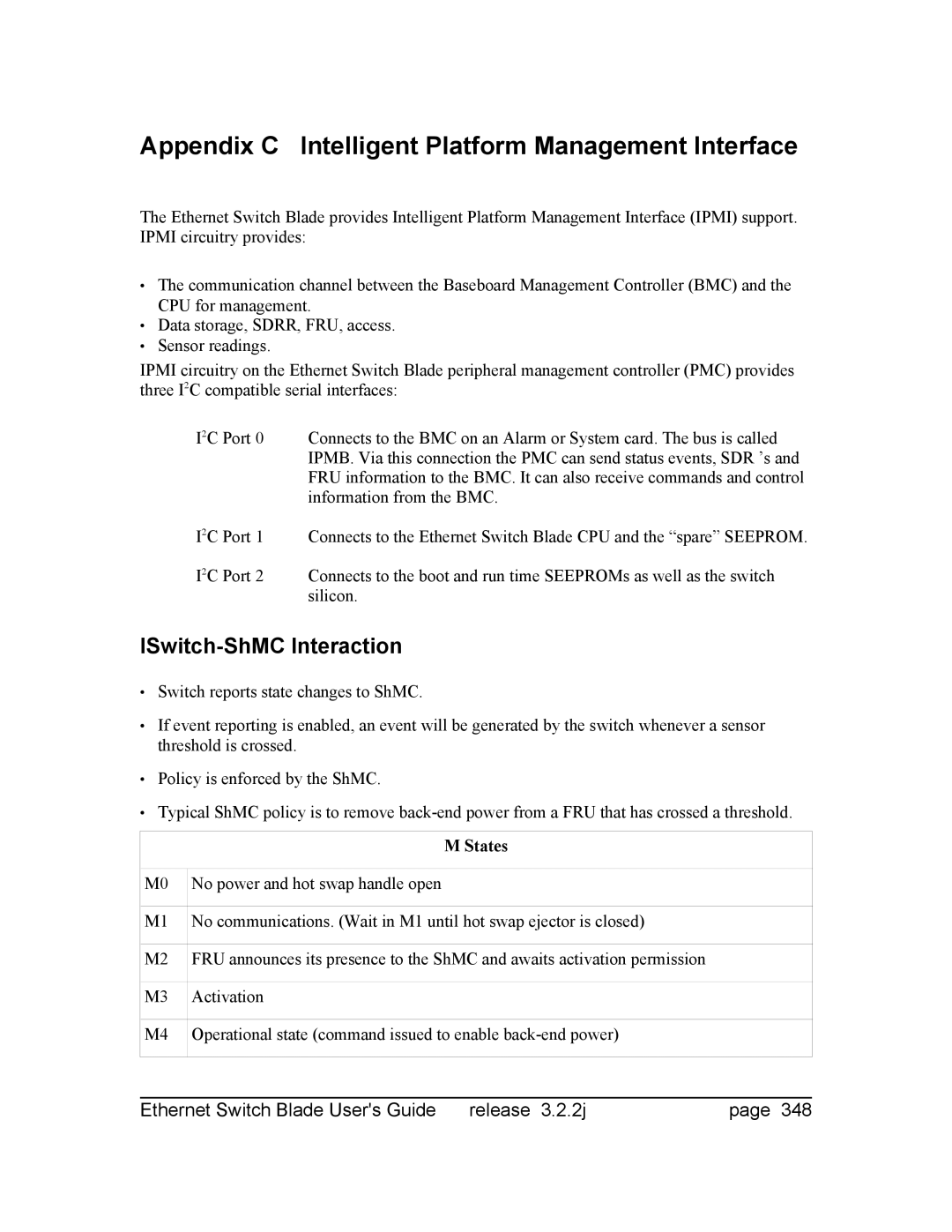
ISwitch-ShMC Interaction
Appendix C Intelligent Platform Management Interface
States
PMC Controller Support Command Code Sensor # Status
Peripheral Management Controller Functional Support
Table C.1. Ipmi M States
Table C.2 PMC Controller Support
Standard Ipmi Command GetSensorReading
Sensor Reading Example
Table C.3 GetSensorReading
Standard Ipmi Response GetSensorReading
Table C.4 GetSensorResonse
Structure of Standard Ipmi Commands From BMC to PMC
Structure of Standard Ipmi Responses From PMC to BMC
Event Generator
Field Replaceable Unit Inventory Device
Ipmb Event message format
Spare Seeprom Space Allocation
Table C.8 Seeprom Space
Ipmb Override Status Data
Table C.9. Ipmb Override Status Data
Index
Dhcp
NFS NTP
Tc 62
Ztmd 301 Zvlan 179 ZX4920.MIB 333