Manuals
/
Agilent Technologies
/
Computer Equipment
/
Computer Drive
Agilent Technologies
U2761A
manual
Product at a Glance, Product Outlook, Bumpers
Models:
U2761A
1
21
123
123
Download
123 pages
57.47 Kb
18
19
20
21
22
23
24
25
Product Characteristics
Install
Trigger Input Signal
Default waveform is Sine wave
Safety Symbols
Dimension
Maintenance
Output Configuration
Set Output Using Scpi Commands
Phase Modulation PM
Page 21
Image 21
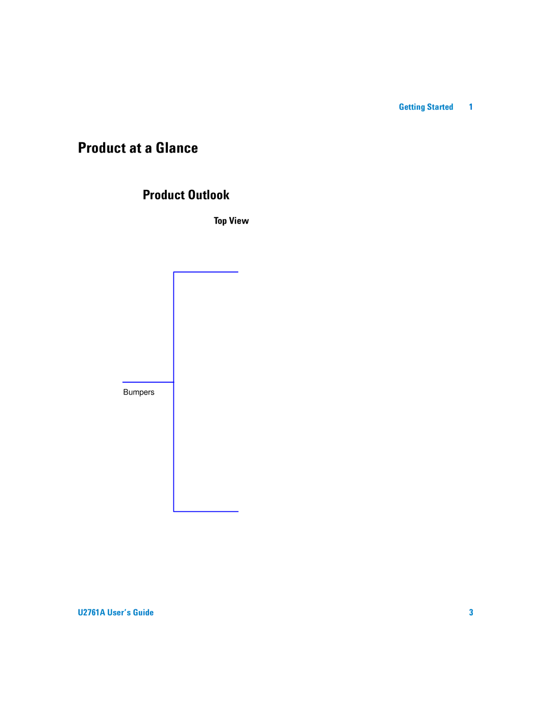
Getting Started
1
Product at a Glance
Product Outlook
Top View
Bumpers
U2761A User’s Guide
3
Page 20
Page 22
Page 21
Image 21
Page 20
Page 22
Contents
User’s Guide
U T I O N Warn in G
Safety Symbols
General Safety Information
Environment Conditions
Complies with the following safety and EMC requirements
Regulatory Markings
Affixed product label is shown as below
Product Category
Declaration of Conformity
Regulatory Information for Australia/New Zealand
This Guide…
Contents
Introduction Output Function
Phase Modulation PM To Select PM
Index
List of Figures
XVI
List of Tables
Xviii
Getting Started
Introduction
Various features of the U2761A
Product at a Glance
Product Outlook
Bumpers
Power inlet
Fan Ventilation Pin backplane connector USB inlet
Dimensions Without Bumpers
Product Dimensions
105.00 mm 175.00 mm 18.00 mm
25.00 mm
Dimensions With Bumpers
117.00 mm 180.00 mm 15.00 mm
41.00 mm
Standard Purchase Items
General Maintenance
Inspection and Maintenance
Initial Inspection
Electrical Check
Installation and Configuration
Installation
With Agilent VEE Pro, LabVIEW, or Microsoft Visual Studio
Hard-disk space 1 GB
Check Your System
Install the IO Libraries Suite
Install the Module Driver
Install the Agilent Measurement Manager
Getting Started
Proceeding
Connect the Module to Your PC
Getting Started
Select Ignore to disable the warning message
Follow the instructions below
Driver Signing Options dialog box will appear
Getting Started
Verify Your Module Connection
Send Commands To This Instrument
Launch Your Agilent Measurement Manager
IO Control will launch automatically when you start your PC
Agilent Measurement Manager help file
Description
Pin Backplane Connector Pin Configuration
Chassis Installation
Triggering
Pulse Waveform
Introduction
Output Configuration
Output Function
1Output functions
Function Limitation
1U2761A soft front panel
Waveform pattern selection Waveform parameters
2Output frequency range
Output Frequency
Function Limitations
Offset Voltage Limitations
Output Amplitude
Limits Due to Units Selection
Limits Due to Amplitude
DC Offset Voltage
VOLTageOFFSet offset
Output Units
Output Termination
OUTPutLOAD ohmsINFinity
7Square wave duty cycles
Duty Cycle Square Waves
APPLy command automatically sets the duty cycle to 50%
9Ramp wave duty cycles
Symmetry Ramp Wave
11Panel view of the output section
Output Control
Example 1, To output a DC voltage
Set Output Using Scpi Commands
Example 2, To output a Sine wave
Example 4, To output a Ramp wave
Pulse Period
Pulse Waveform
13Panel view of the pulse width section
Pulse Width
Duty Cycle = 100 ⋅ Pulse Width / Period
Pulse Duty Cycle
Example
Generate Pulse Waveform Using Scpi Commands
Amplitude Modulation AM
To Select AM
Modulating frequency AM depth
15Panel view of AM
Carrier Waveform
3Carrier frequency for AM
Carrier Frequency
Modulating Waveform
Default modulating waveform is Sine wave
Modulating Waveform Frequency
Modulation Depth
Peak into a 50 Ω load
Generate AM Using Scpi Commands
Frequency Modulation FM
To Select FM
Modulating frequency FM deviation
FMSTATe Offon
4Carrier frequency for FM
FMINTernalFUNCtion SINusoidSQUareRAMPNRAMpTRIangleUSER
Frequency Deviation
Generate FM Using Scpi Commands
Phase Modulation PM
Modulating frequency Phase deviation
To Select PM
PMSTATe Offon
5Carrier frequency for PM
Default waveform is Sine wave
Generate PM Using Scpi Commands
Phase Deviation
Frequency-Shift Keying FSK Modulation
To Select FSK Modulation
FSK rate Hop frequency
FSKeySTATe Offon
6Carrier frequency for FSK
FSK Carrier Frequency
7Hop frequency
FSK Hop Frequency
FSK Rate
Generate FSK Modulation Using Scpi Commands
Phase-Shift Keying PSK Modulation
To Select PSK Modulation
PSK rate PSK deviation
PSKeySTATe Offon
8Carrier frequency for PSK
PSK Carrier Frequency
PSK Deviation
PSK Rate
Generate PSK Modulation Using Scpi Commands
Amplitude-Shift Keying ASK Modulation
To Select ASK Modulation
ASK rate
ASKeySTATe Offon
9Carrier frequency for ASK
ASK Rate
Generate ASK Modulation Using Scpi Commands
Frequency Sweep
To Select Sweep
Frequency Linear type Start frequency Stop frequency
28Panel view of sweep
Start Frequency and Stop Frequency
Sweep Time
Sweep Mode
Sweep Trigger Source
Set Frequency Sweep Using Scpi Commands
Trigger Source Choices
Triggering
Manual Triggering
Internal Triggering
External Triggering
Trigger Output Signal
Trigger Input Signal
Trigger Rising edge shown
Trigger out 500 μs Rising edge shown
OUTPutTRIGger Offon OUTPutTRIGgerSLOPe POSitiveNEGative
Set Triggering Using Scpi Commands
To Create and Store an Arbitrary Waveform
Arbitrary Waveforms
Select the Arbitrary waveform function
Exiting the waveform editor
Features and Functions
Characteristics and Specifications
Operating Environment
Product Characteristics
Waveforms
Product Specifications and Characteristics
Ramp, Triangle
±1% of settling ±5 mV ±10 mV @ Hi-Z
Units Vpp, Vrms, dBm Resolution Digits
±5 V across open circuit
Accuracy ±8 ppm in 1 year
Modulation
Sweep Characteristics
102
Index
Offset. Refer to DC offset
United States Tel 800 829
Top
Page
Image
Contents