Features and Functions | 2 |
Phase Modulation (PM)
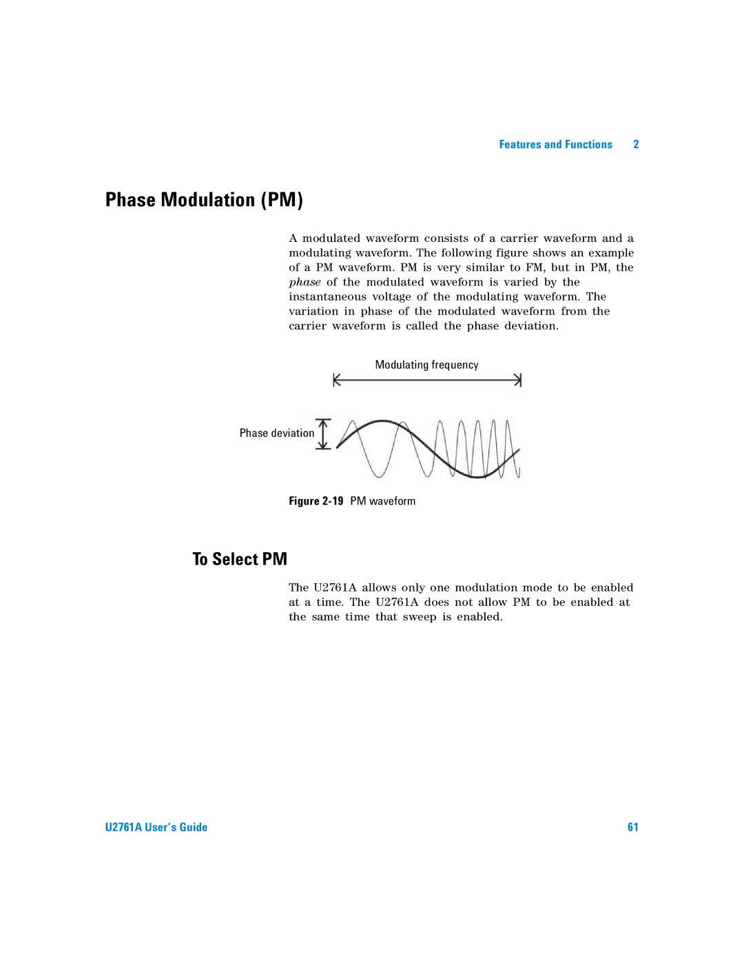
A modulated waveform consists of a carrier waveform and a modulating waveform. The following figure shows an example of a PM waveform. PM is very similar to FM, but in PM, the phase of the modulated waveform is varied by the instantaneous voltage of the modulating waveform. The variation in phase of the modulated waveform from the carrier waveform is called the phase deviation.
Modulating frequency
Phase deviation
Figure 2-19 PM waveform
To Select PM
The U2761A allows only one modulation mode to be enabled at a time. The U2761A does not allow PM to be enabled at the same time that sweep is enabled.
U2761A User’s Guide | 61 |