Getting Started | 1 |
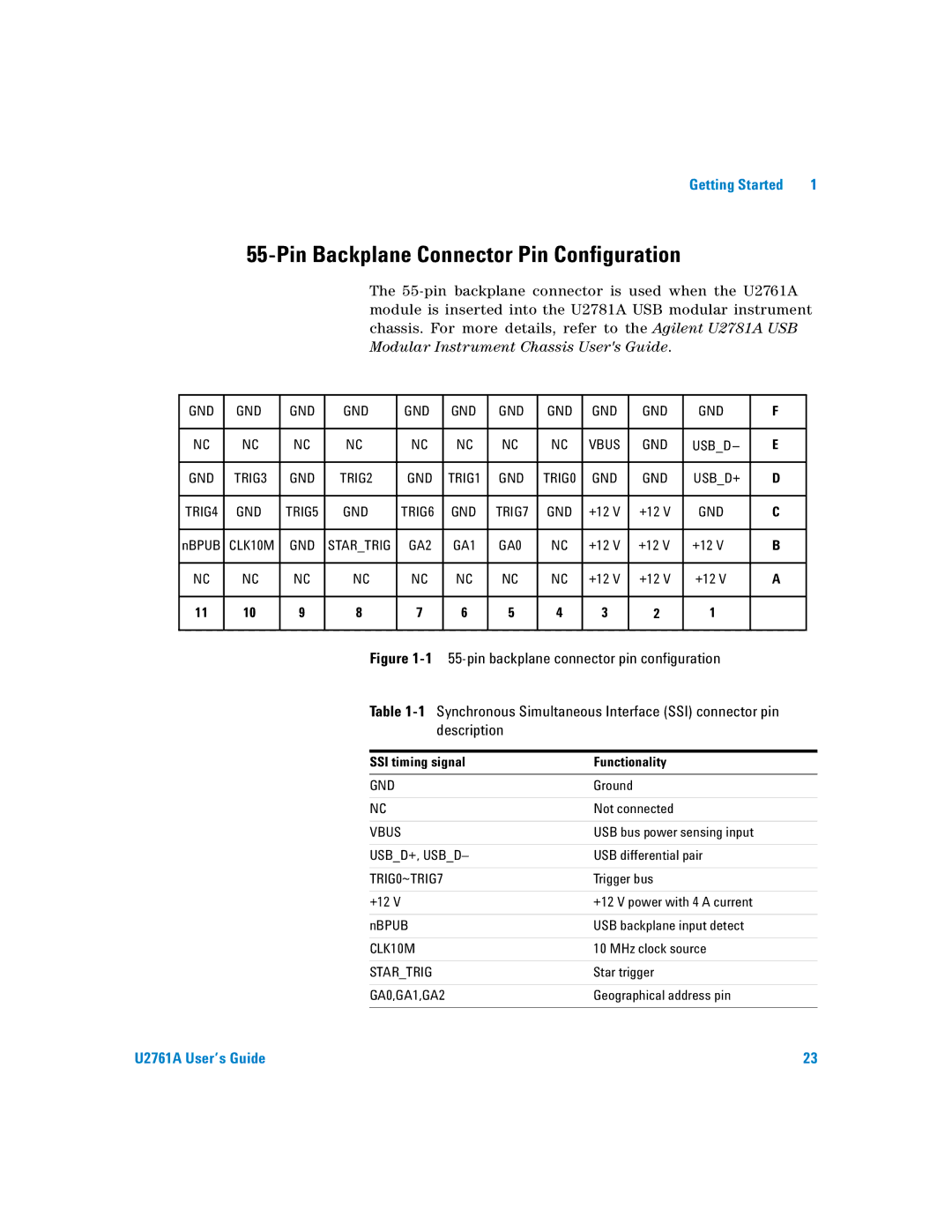
55-Pin Backplane Connector Pin Configuration
The
GND | GND | GND | GND |
| GND |
| GND | GND | GND | GND |
| GND | GND |
| F |
| |
|
|
|
|
|
|
|
|
|
|
|
|
|
|
|
|
|
|
NC | NC | NC | NC |
| NC |
| NC | NC | NC | VBUS |
| GND | USB_D– |
| E |
| |
|
|
|
|
|
|
|
|
|
|
|
|
|
|
|
|
|
|
GND | TRIG3 | GND | TRIG2 |
| GND |
| TRIG1 | GND | TRIG0 | GND |
| GND | USB_D+ |
| D |
| |
|
|
|
|
|
|
|
|
|
|
|
|
|
|
|
|
|
|
TRIG4 | GND | TRIG5 | GND |
| TRIG6 |
| GND | TRIG7 | GND | +12 V |
| +12 V | GND |
| C |
| |
|
|
|
|
|
|
|
|
|
|
|
|
|
|
|
|
|
|
nBPUB | CLK10M | GND | STAR_TRIG |
| GA2 |
| GA1 | GA0 | NC | +12 V |
| +12 V | +12 V |
| B |
| |
|
|
|
|
|
|
|
|
|
|
|
|
|
|
|
|
|
|
NC | NC | NC | NC |
| NC |
| NC | NC | NC | +12 V |
| +12 V | +12 V |
| A |
| |
|
|
|
|
|
|
|
|
|
|
|
|
|
|
|
|
|
|
11 | 10 | 9 | 8 |
|
| 7 |
| 6 | 5 | 4 | 3 |
| 2 | 1 |
|
|
|
|
|
|
|
|
|
|
|
|
|
|
|
|
|
| |||
|
|
|
| Figure |
|
| |||||||||||
|
|
|
| Table |
| ||||||||||||
|
|
|
|
|
| description |
|
|
|
|
|
|
|
| |||
|
|
|
|
|
|
|
|
|
|
|
| ||||||
|
|
|
| SSI timing signal |
|
| Functionality |
|
|
|
| ||||||
|
|
|
|
|
|
|
|
|
|
|
|
|
|
|
| ||
|
|
|
| GND |
|
|
|
|
| Ground |
|
|
|
|
| ||
|
|
|
|
|
|
|
|
|
|
|
|
|
|
| |||
|
|
|
| NC |
|
|
|
|
| Not connected |
|
|
|
| |||
|
|
|
|
|
|
|
|
|
|
|
|
| |||||
|
|
|
| VBUS |
|
|
|
|
| USB bus power sensing input |
|
| |||||
|
|
|
|
|
|
|
|
|
| ||||||||
|
|
|
| USB_D+, USB_D– |
|
| USB differential pair |
|
| ||||||||
|
|
|
|
|
|
|
|
|
|
|
|
| |||||
|
|
|
| TRIG0~TRIG7 |
|
|
| Trigger bus |
|
|
|
| |||||
|
|
|
|
|
|
|
|
|
|
|
|
| |||||
|
|
|
| +12 V |
|
|
|
|
| +12 V power with 4 A current |
|
| |||||
|
|
|
|
|
|
|
|
|
|
| |||||||
|
|
|
| nBPUB |
|
|
| USB backplane input detect |
|
| |||||||
|
|
|
|
|
|
|
|
|
|
| |||||||
|
|
|
| CLK10M |
|
|
| 10 MHz clock source |
|
| |||||||
|
|
|
|
|
|
|
|
|
|
|
|
| |||||
|
|
|
| STAR_TRIG |
|
|
| Star trigger |
|
|
|
| |||||
|
|
|
|
|
|
|
|
|
|
| |||||||
|
|
|
| GA0,GA1,GA2 |
|
|
| Geographical address pin |
|
| |||||||
|
|
|
|
|
|
|
|
|
|
|
|
|
|
|
|
|
|
U2761A User’s Guide | 23 |