2 Features and Functions
Trigger Input Signal
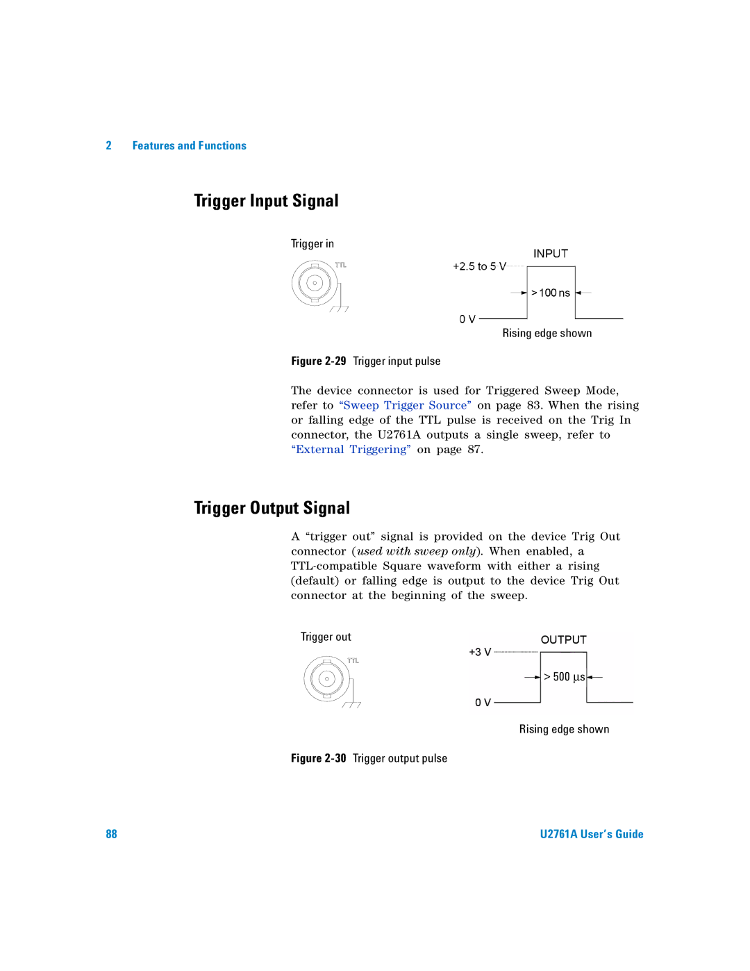
Trigger in
Rising edge shown
Figure 2-29 Trigger input pulse
The device connector is used for Triggered Sweep Mode, refer to “Sweep Trigger Source” on page 83. When the rising or falling edge of the TTL pulse is received on the Trig In connector, the U2761A outputs a single sweep, refer to “External Triggering” on page 87.
Trigger Output Signal
A “trigger out” signal is provided on the device Trig Out connector (used with sweep only). When enabled, a
Trigger out
> 500 μs
Rising edge shown
Figure 2-30 Trigger output pulse
88 | U2761A User’s Guide |