Configuring High Availability VLANs
Application Example 2: Inter-Switch HA VLANs
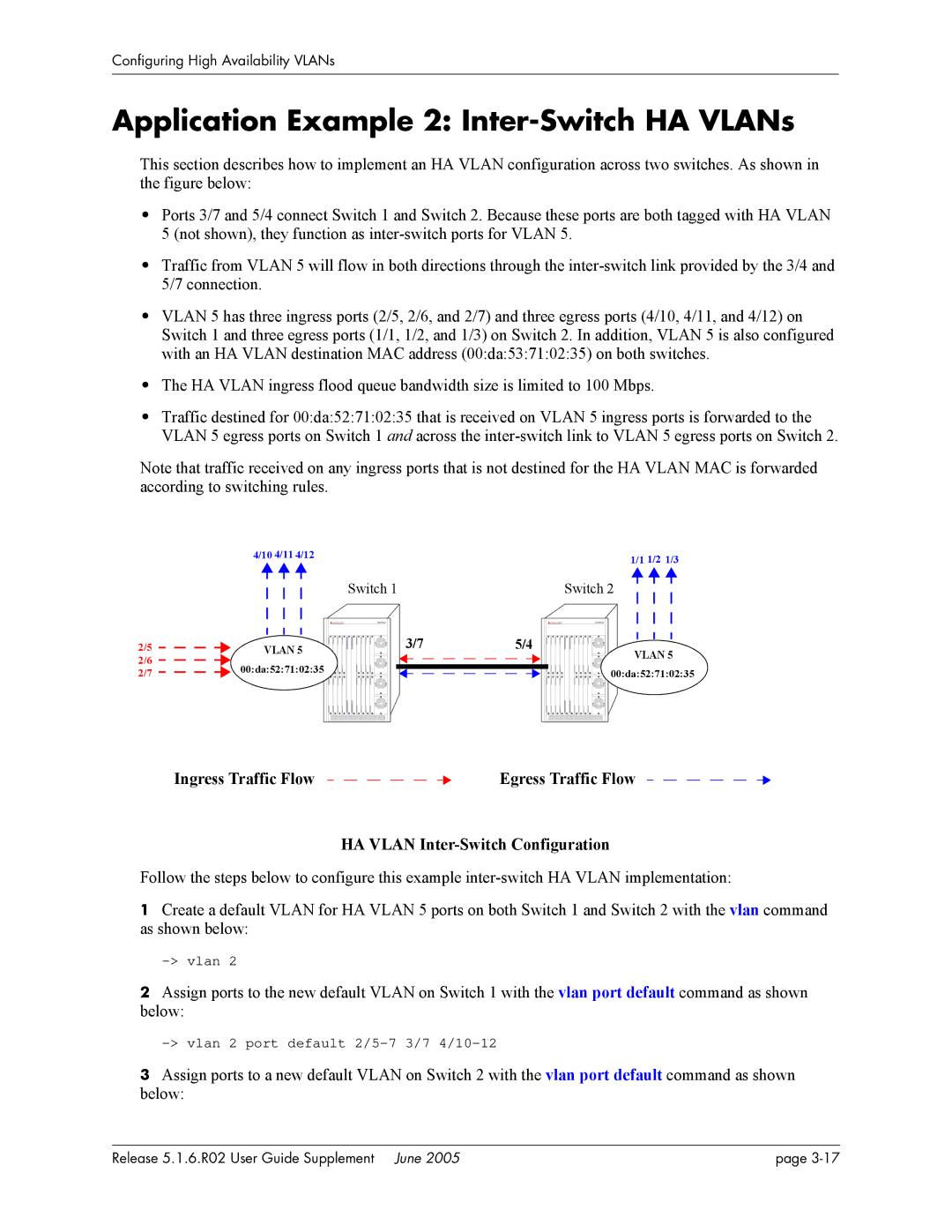
This section describes how to implement an HA VLAN configuration across two switches. As shown in the figure below:
•Ports 3/7 and 5/4 connect Switch 1 and Switch 2. Because these ports are both tagged with HA VLAN 5 (not shown), they function as
•Traffic from VLAN 5 will flow in both directions through the
•VLAN 5 has three ingress ports (2/5, 2/6, and 2/7) and three egress ports (4/10, 4/11, and 4/12) on Switch 1 and three egress ports (1/1, 1/2, and 1/3) on Switch 2. In addition, VLAN 5 is also configured with an HA VLAN destination MAC address (00:da:53:71:02:35) on both switches.
•The HA VLAN ingress flood queue bandwidth size is limited to 100 Mbps.
•Traffic destined for 00:da:52:71:02:35 that is received on VLAN 5 ingress ports is forwarded to the VLAN 5 egress ports on Switch 1 and across the
Note that traffic received on any ingress ports that is not destined for the HA VLAN MAC is forwarded according to switching rules.
4/10 4/11 4/12 |
|
|
|
|
| 1/1 1/2 1/3 | ||||||||||
|
|
|
|
|
|
|
|
| ||||||||
|
|
|
|
|
|
|
|
|
|
|
|
|
|
|
|
|
|
|
|
|
| Switch 1 |
| Switch 2 |
|
|
| ||||||
|
|
|
|
|
| |||||||||||
|
|
|
|
|
|
|
|
|
|
|
|
|
|
|
|
|
|
|
|
|
|
|
|
|
|
|
|
|
|
|
|
|
|
|
|
|
|
|
|
|
|
|
|
|
|
|
|
|
|
|
|
|
|
|
|
|
|
|
|
|
|
|
|
|
|
|
|
|
|
|
|
|
|
|
|
|
|
|
|
|
|
|
|
|
2/5 | VLAN 5 | 3/7 | 5/4 |
2/6 | 00:da:52:71:02:35 |
|
|
2/7 |
|
| |
|
|
|
VLAN 5 |
00:da:52:71:02:35 |
Ingress Traffic Flow |
|
|
|
|
|
|
|
|
|
|
| Egress Traffic Flow |
|
|
|
|
|
|
HA VLAN Inter-Switch Configuration
Follow the steps below to configure this example
1Create a default VLAN for HA VLAN 5 ports on both Switch 1 and Switch 2 with the vlan command as shown below:
2Assign ports to the new default VLAN on Switch 1 with the vlan port default command as shown below:
3Assign ports to a new default VLAN on Switch 2 with the vlan port default command as shown below:
Release 5.1.6.R02 User Guide Supplement June 2005 | page |