ATS Component Details
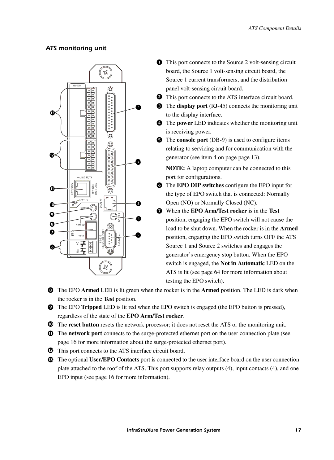
ATS monitoring unit
This port connects to the Source 2
| board, the Source 1 |
| Source 1 current transformers, and the distribution |
8 8 5- 22 8 8 | panel |
|
This port connects to the ATS interface circuit board.
The display port
to the display interface.
The power LED indicates whether the monitoring unit
|
|
|
|
|
| is receiving power. | |
|
|
|
|
|
| The console port | |
|
|
| 1 | 4 |
| relating to servicing and for communication with the | |
|
|
|
| 1 |
| generator (see item 4 on page page 13). | |
|
| 2 |
|
| |||
|
|
| 1 5 |
| |||
|
| 3 |
|
| |||
|
|
| 6 |
| |||
|
|
| 4 | 1 |
| ||
|
|
|
| | |||
|
|
|
| 1 7 | |||
|
|
| 5 |
|
| ||
|
|
| 6 | 1 8 | NOTE: A laptop computer can be connected to this | ||
|
|
|
|
| |||
|
|
|
| 1 |
| ||
|
|
| 7 |
|
| ||
|
|
| 8 | 2 0 |
| ||
|
|
|
|
| |||
|
|
|
| 2 1 |
| ||
|
| LIN K RX/TX | 2 1 1 1 0 9 | 2 4 2 3 2 2 |
| port for configurations. | |
|
|
|
| ||||
|
|
| 1 | 2 5 |
| The EPO DIP switches configure the EPO input for | |
| N E T O R K | 1 0 = G R N 1 0 0 = O R N |
|
| |||
| 1 3 |
|
| ||||
|
| the type of EPO switch that is connected: Normally | |||||
|
|
| |||||
|
|
|
|
|
| ||
| R E T | STATU S | IS PL A Y |
| | Open (NO) or Normally Closed (NC). | |
| TR |
| |||||
|
| D |
|
| When the EPO Arm/Test rocker is in the Test | ||
|
|
| R |
| |||
|
|
| PO E | | position, engaging the EPO switch will not cause the | ||
|
| A RM ED |
| ||||
|
|
|
| load to be shut down. When the rocker is in the Armed | |||
| EPO |
| R | 9 6 00 |
| ||
TE ST | | position, engaging the EPO switch turns OFF the ATS | |||||
| |||||||
|
|
| |||||
| N C |
| Source 1 and Source 2 switches and engages the | ||||
|
| N O |
|
|
| generator’s emergency stop button. When the EPO | |
|
|
|
|
|
|
switch is engaged, the Not in Automatic LED on the ATS is lit (see page 64 for more information about testing the EPO switch).
The EPO Armed LED is lit green when the rocker is in the Armed position. The LED is dark when
the rocker is in the Test position.
The EPO Tripped LED is lit red when the EPO switch is engaged (the EPO button is pressed), regardless of the state of the EPO Arm/Test rocker.
The reset button resets the network processor; it does not reset the ATS or the monitoring unit.
The network port connects to the
This port connects to the ATS interface circuit board.
The optional User/EPO Contacts port is connected to the user interface board on the user connection plate attached to the roof of the ATS. This port supports relay outputs (4), input contacts (4), and one
EPO input (see page 16 for more information).
InfraStruXure Power Generation System | 17 |