ATS Component Details
Automatic operation control panel
For more detailed information concerning Automatic Operation of the InfraStruXure Power Generation System, see “Automatic Operation” on page 19.
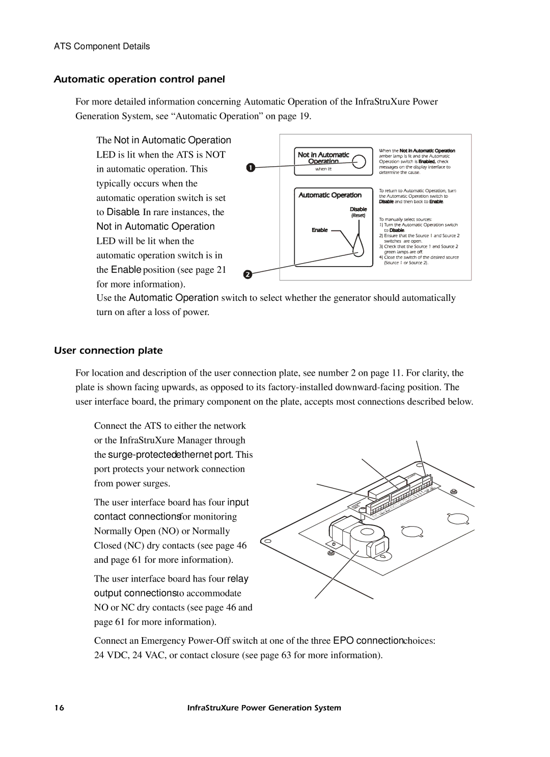
The Not in Automatic Operation
LED is lit when the ATS is NOT in automatic operation. This typically occurs when the automatic operation switch is set to Disable. In rare instances, the
Not in Automatic Operation
LED will be lit when the automatic operation switch is in the Enable position (see page 21 for more information).
Use the Automatic Operation switch to select whether the generator should automatically turn on after a loss of power.
User connection plate
For location and description of the user connection plate, see number 2 on page 11. For clarity, the plate is shown facing upwards, as opposed to its
Connect the ATS to either the network or the InfraStruXure Manager through the
The user interface board has four input contact connections for monitoring Normally Open (NO) or Normally Closed (NC) dry contacts (see page 46 and page 61 for more information).
The user interface board has four relay output connections to accommodate NO or NC dry contacts (see page 46 and page 61 for more information).
Connect an Emergency
16 | InfraStruXure Power Generation System |