How to Add
Allowed circuit breaker combinations
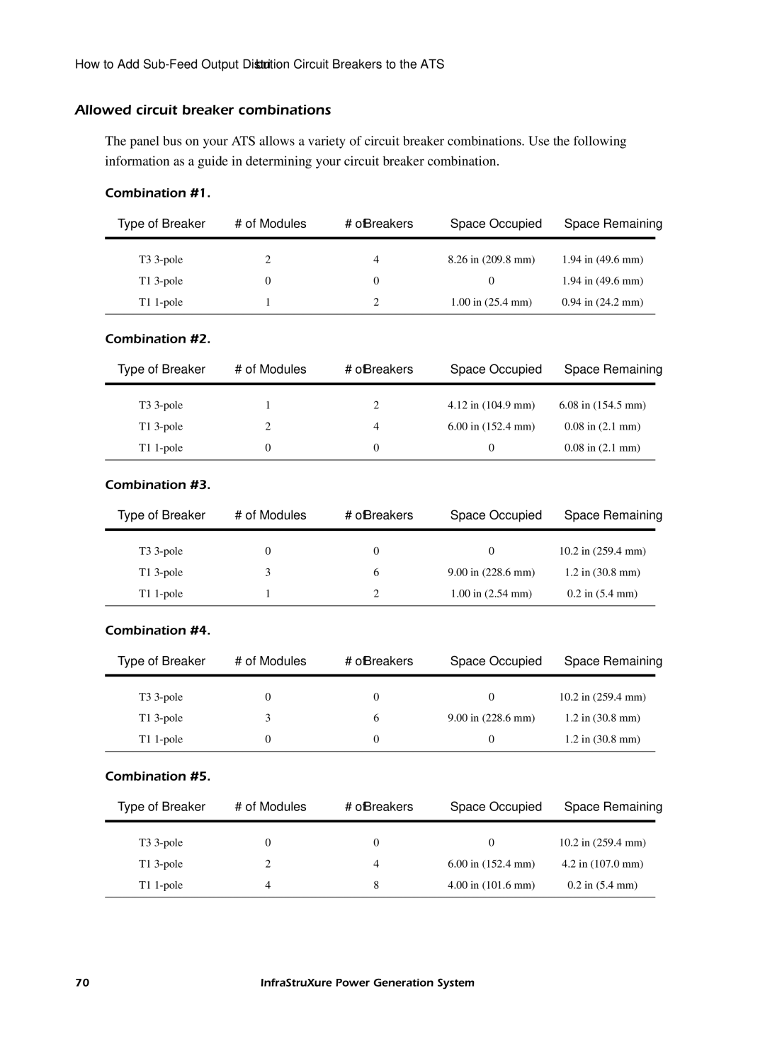
The panel bus on your ATS allows a variety of circuit breaker combinations. Use the following information as a guide in determining your circuit breaker combination.
Combination #1.
Type of Breaker | # of Modules | # of Breakers | Space Occupied | Space Remaining |
|
|
|
|
|
T3 | 2 | 4 | 8.26 in (209.8 mm) | 1.94 in (49.6 mm) |
T1 | 0 | 0 | 0 | 1.94 in (49.6 mm) |
T1 | 1 | 2 | 1.00 in (25.4 mm) | 0.94 in (24.2 mm) |
|
|
|
|
|
Combination #2.
Type of Breaker | # of Modules | # of Breakers | Space Occupied | Space Remaining |
|
|
|
|
|
T3 | 1 | 2 | 4.12 in (104.9 mm) | 6.08 in (154.5 mm) |
T1 | 2 | 4 | 6.00 in (152.4 mm) | 0.08 in (2.1 mm) |
T1 | 0 | 0 | 0 | 0.08 in (2.1 mm) |
|
|
|
|
|
Combination #3.
Type of Breaker | # of Modules | # of Breakers | Space Occupied | Space Remaining |
|
|
|
|
|
T3 | 0 | 0 | 0 | 10.2 in (259.4 mm) |
T1 | 3 | 6 | 9.00 in (228.6 mm) | 1.2 in (30.8 mm) |
T1 | 1 | 2 | 1.00 in (2.54 mm) | 0.2 in (5.4 mm) |
|
|
|
|
|
Combination #4.
Type of Breaker | # of Modules | # of Breakers | Space Occupied | Space Remaining |
|
|
|
|
|
T3 | 0 | 0 | 0 | 10.2 in (259.4 mm) |
T1 | 3 | 6 | 9.00 in (228.6 mm) | 1.2 in (30.8 mm) |
T1 | 0 | 0 | 0 | 1.2 in (30.8 mm) |
|
|
|
|
|
Combination #5.
Type of Breaker | # of Modules | # of Breakers | Space Occupied | Space Remaining |
|
|
|
|
|
T3 | 0 | 0 | 0 | 10.2 in (259.4 mm) |
T1 | 2 | 4 | 6.00 in (152.4 mm) | 4.2 in (107.0 mm) |
T1 | 4 | 8 | 4.00 in (101.6 mm) | 0.2 in (5.4 mm) |
|
|
|
|
|
70 | InfraStruXure Power Generation System |
