ATS/Voltage
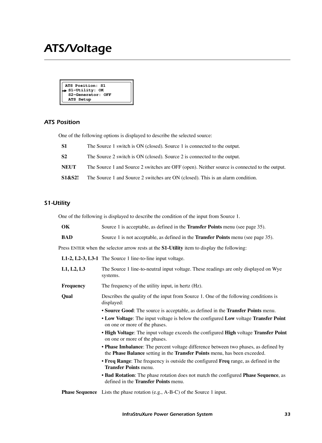
ATS Position: S1
![]()
![]()
ATS Setup
ATS Position
One of the following options is displayed to describe the selected source:
S1 | The Source 1 switch is ON (closed). Source 1 is connected to the output. |
S2 | The Source 2 switch is ON (closed). Source 2 is connected to the output. |
NEUT | The Source 1 and Source 2 switches are OFF (open). Neither source is connected to the output. |
S1&S2! | The Source 1 and Source 2 switches are ON (closed). This is an alarm condition. |
S1-Utility
One of the following is displayed to describe the condition of the input from Source 1.
OK | Source 1 is acceptable, as defined in the Transfer Points menu (see page 35). |
BAD | Source 1 is not acceptable, as defined in the Transfer Points menu (see page 35). |
Press ENTER when the selector arrow rests at the
L1, L2, L3 The Source 1
Frequency The frequency of the utility input, in hertz (Hz).
Qual Describes the quality of the input from Source 1. One of the following conditions is displayed:
•Source Good: The source is acceptable, as defined in the Transfer Points menu.
•Low Voltage: The input voltage is below the configured Low voltage Transfer Point on one or more of the phases.
•High Voltage: The input voltage exceeds the configured High voltage Transfer Point on one or more of the phases.
•Phase Imbalance: The percent voltage difference between two phases, as defined by the Phase Balance setting in the Transfer Points menu, has been exceeded.
•Freq Range: The frequency is outside the configured Freq range, as defined in the Transfer Points menu.
•Bad Rotation: The phase rotation does not match the configured Phase Sequence, as defined in the Transfer Points menu.
Phase Sequence Lists the phase rotation (e.g.,
InfraStruXure Power Generation System | 33 |