InfraStruXure Power Generation System
46
† If you map all three of the voltage alarms (V1, V2, Vo), the map will display the following: V12o
‡ If you map all four of the contact alarms (C1, C2, C3, C4), the map will display the following: C1234
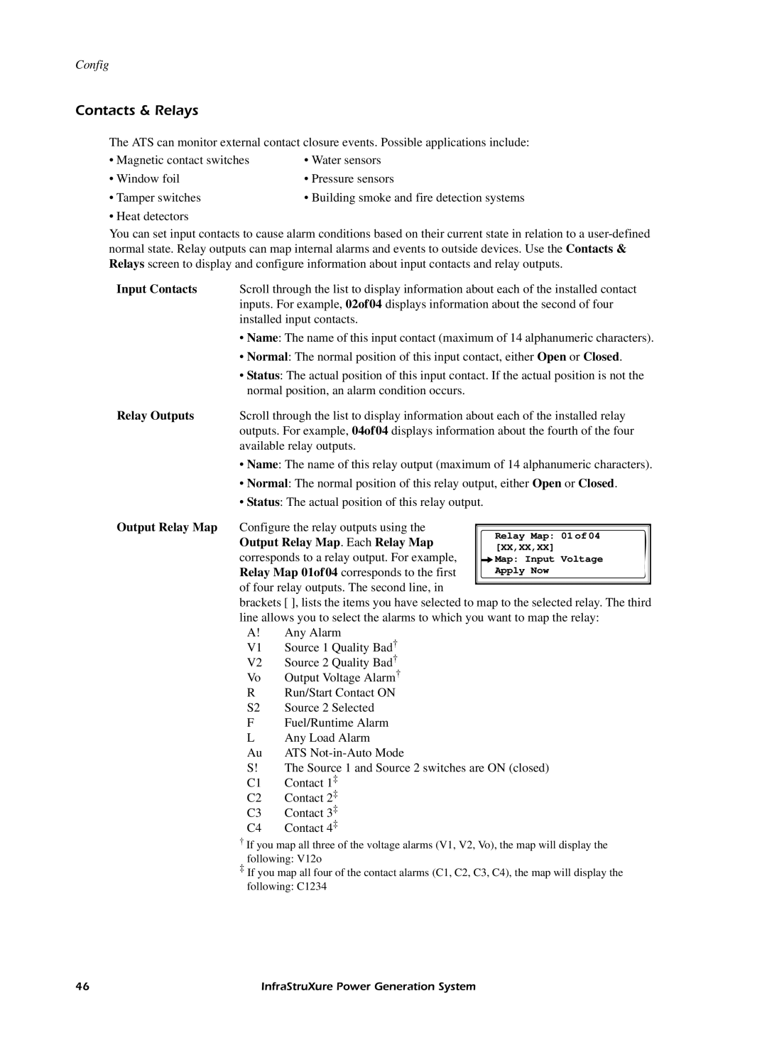
Relay Map: 01 of 04 [XX,XX,XX]
Map: Input Voltage Apply Now
Output Relay Map
Configure the relay outputs using the Output Relay Map. Each Relay Map corresponds to a relay output. For example, Relay Map 01of04 corresponds to the first
of four relay outputs. The second line, in
brackets [ ], lists the items you have selected to map to the selected relay. The third line allows you to select the alarms to which you want to map the relay:
A! Any Alarm
V1 Source 1 Quality Bad†
V2 Source 2 Quality Bad†
Vo Output Voltage Alarm†
R Run/Start Contact ON S2 Source 2 Selected
F Fuel/Runtime Alarm
L Any Load Alarm
Au ATS Not-in-Auto Mode
S! The Source 1 and Source 2 switches are ON (closed)
C1 Contact 1‡
C2 Contact 2‡
C3 Contact 3‡
C4 Contact 4‡
Scroll through the list to display information about each of the installed relay outputs. For example, 04of04 displays information about the fourth of the four available relay outputs.
• Name: The name of this relay output (maximum of 14 alphanumeric characters).
• Normal: The normal position of this relay output, either Open or Closed.
• Status: The actual position of this relay output.
Relay Outputs
• Heat detectors
You can set input contacts to cause alarm conditions based on their current state in relation to a user-defined normal state. Relay outputs can map internal alarms and events to outside devices. Use the Contacts & Relays screen to display and configure information about input contacts and relay outputs.
Input Contacts Scroll through the list to display information about each of the installed contact inputs. For example, 02of04 displays information about the second of four installed input contacts.
• Name: The name of this input contact (maximum of 14 alphanumeric characters).
• Normal: The normal position of this input contact, either Open or Closed.
• Status: The actual position of this input contact. If the actual position is not the normal position, an alarm condition occurs.
• Tamper switches
• Building smoke and fire detection systems
• Window foil
• Pressure sensors
• Magnetic contact switches
• Water sensors
Config
Contacts & Relays
The ATS can monitor external contact closure events. Possible applications include:
