MAX Servers - Setup and Configuration
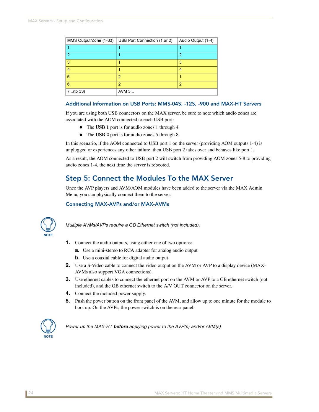
MMS Output/Zone | USB Port Connection (1 or 2) | Audio Output |
|
|
|
1 | 1 | 1‘ |
2 | 1 | 2 |
3 | 1 | 3 |
4 | 1 | 4 |
5 | 2 | 1 |
6 | 2 | 2 |
7...(to 33) | AVM 3... |
|
|
|
|
Additional Information on USB Ports:
If you are using both USB connectors on the MAX server, be sure to note which audio zones are associated with the AOM connected to each USB port:
The USB 1 port is for audio zones 1 through 4.
The USB 2 port is for audio zones 5 through 8.
In this scenario, if the AOM connected to USB port 1 on the server (providing AOM outputs
As a result, the AOM connected to USB port 2 will switch from providing AOM zones
Step 5: Connect the Modules To the MAX Server
Once the AVP players and AVM/AOM modules have been added to the server via the MAX Admin Menu, you can physically connect them to the server:
Connecting MAX-AVPs and/or MAX-AVMs
Multiple AVMs/AVPs require a GB Ethernet switch (not included).
1.Connect the audio outputs, using either one of two options:
a.Use a
b.Use a coaxial cable for digital audio output
2.Use a
3.Use ethernet cables to connect the ethernet port on the AVM or AVP to a GB ethernet switch (not included), and the GB ethernet switch to the A/V OUT connector on the server.
4.Connect the included power supply.
5.Push the power button on the front panel of the AVM, and allow up to one minute for the module to boot up. On the AVPs, the power switch is on the rear panel.
Power up the
24 | MAX Servers: HT Home Theater and MMS Multimedia Servers |