Section 4 Talker Output Format
4.1Talker Output Response Message Format
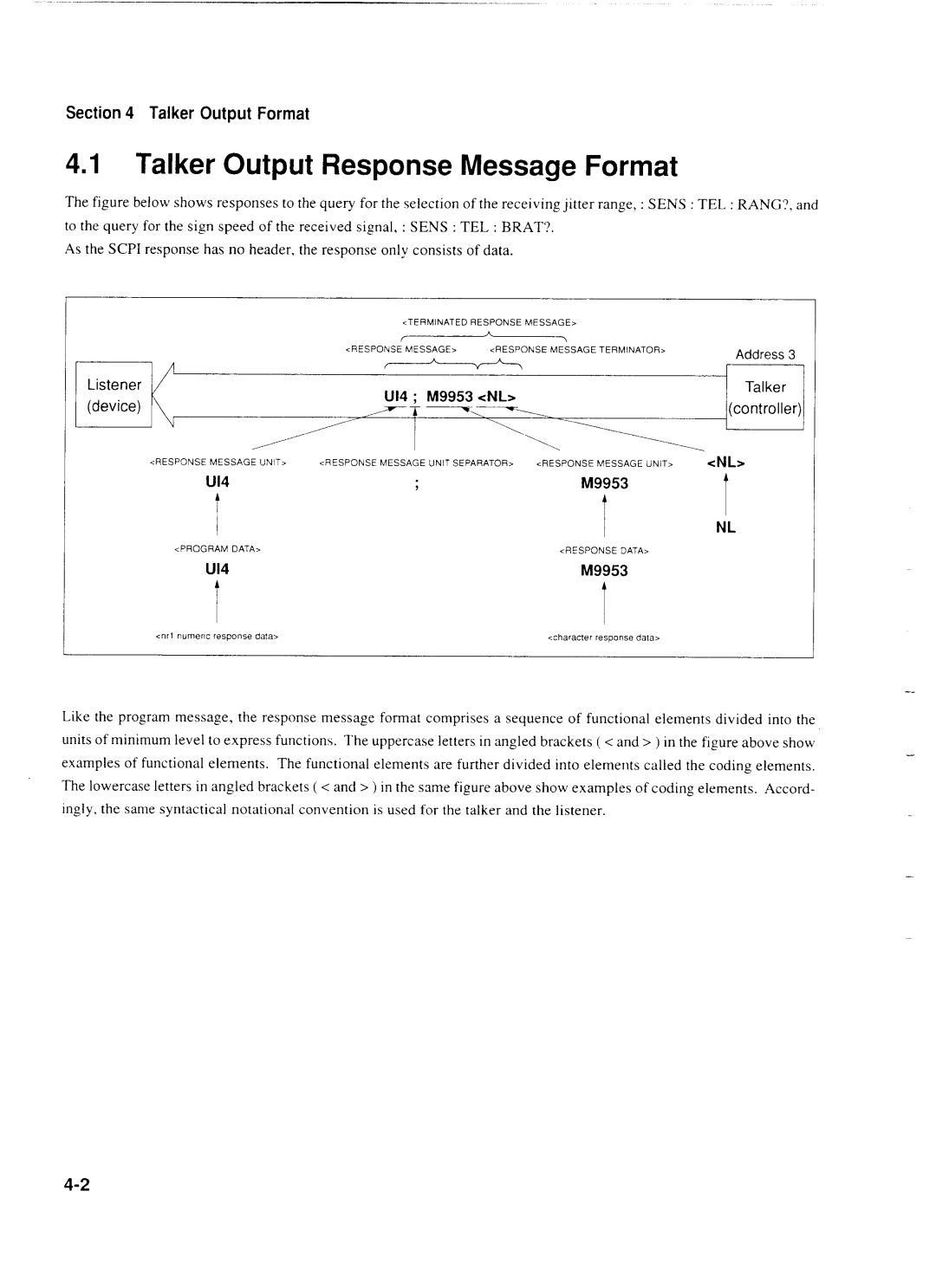
The figure below shows responses to the query for the selection of the receiving jitter range, : SENS : TEL : RANG?, and
to the query for the sign speed of the received signal, : SENS : TEL : BRAT?. As the SCPI response has no header, the response only consists of data.
| <TERMINATED RESPONSE MESSAGE, |
|
| ||
| <RESPONSE MESSAGE> | <RESPONSE MESSAGE TERMINATOR, | Address 3 | ||
| - |
| |||
Listener |
| Talker | |||
(device) | U14 ; M9953 <NL> |
|
|
| |
r~I--- |
| (controller) | |||
| - - - - I |
| 1.. | 1 | |
<RESPONSE MESSAGE UNIT> | <RESPONSE MESSAGE UNIT SEPARATOR> | <RESPONSE MESSAGE UNIT> | <NL> | ||
U14 | 9 |
| M9953 | t | |
c n r l numerlc response data> | <character response data, |
Like the program message, the response message format comprises a sequence of functional elements divided into the units of minimum level to express functions. The uppercase letters in angled brackets ( < and > ) in the figure above show examples of functional elements. The functional elements are further divided into elements called the coding elements. The lowercase letters in angled brackets ( < and > ) in the same figure above show examples of coding elements. Accord- ingly, the same syntactical notational convention is used for the talker and the listener.