102DSR Switch Installer/User Guide
Appendix E: Cable Pinout Information
NOTE: Only the DSR1024, DSR2035 and DSR8035 switches have the
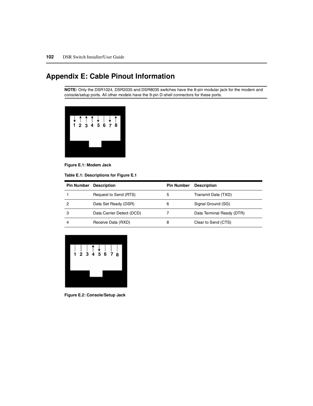
1 2 3 4 5 6 7 8
Figure E.1: Modem Jack
Table E.1: Descriptions for Figure E.1
Pin Number | Description | Pin Number | Description |
|
|
|
|
1 | Request to Send (RTS) | 5 | Transmit Data (TXD) |
|
|
|
|
2 | Data Set Ready (DSR) | 6 | Signal Ground (SG) |
|
|
|
|
3 | Data Carrier Detect (DCD) | 7 | Data Terminal Ready (DTR) |
|
|
|
|
4 | Receive Data (RXD) | 8 | Clear to Send (CTS) |
|
|
|
|
1 2 3 4 5 6 7 8