2000 Series
Control Panels
About This Manual
Using this Guide for Keypad Programming
E Version Control Panels
Bosch Security Systems 7/05 35114F
2000 Series Program Entry Guide Contents
Contents
An Example, Entering Custom Text
Bosch Security Systems 7/05 35114F
Figures
Tables
2000 Series Program Entry Guide Contents
System Configuration
1.0 System Configuration
3 Keyswitch
2000 Series Program Entry Guide
System Configuration
6 Custom Service Text
Default Blank
2000 Series Program Entry Guide
2.1Phone Routing Set to No
2.0 Phone
Phone Routing Set to Yes
Phone
6 Non-FireRoute
5 Fire Route
7 Pt Trbl Route
8 Restoral Route
12 Sys Trbl Route
11 Cancel Route
13 Sys Trbl Route
14 Duress Route
Default: Local
15 Test Route
2000 Series Program Entry Guide
Phone
Reports
3.0 Reports
1 O/C Rpts - All On
3 Restricted O/C
6 Restoral Rpts
5 Cancel Rpt
7 AC Fail Buzz/Rpt
2000 Series Program Entry Guide
Default
8 Point User Flag
2000 Series Program Entry Guide
Reports
Reports
2000 Series Program Entry Guide
EN
Bosch Security Systems | 7/05 | 35114F
4.1Modem Reports
4.0Receiver
Receiver
1 Rcvr Format
Receiver
2000 Series Program Entry Guide
EN
Table 2 continued
Receiver
2000 Series Program Entry Guide
EN
Table 2 continued
1 - Account number 2 - Report group
4.2Pulse Report Groups
3 - Point, user
2 Fire Group
3 Non-FireGroup
8 Cancel Group
4 Pt Trbl Group
5 Restoral Group
11 Duress Group
10 Sys Res Group
12 Test Group
2000 Series Program Entry Guide
Remote Programming
5.0 Remote Programming
1 RAM Passcode
2 RAM Phone
2000 Series Program Entry Guide
Remote Programming
EN
Open/Close
6.0 Open/Close
1 Entry Dly Time
2 Exit Dly Time
5 No Delay
6.1Step Outside
6 Excursion
2000 Series Program Entry Guide
6.2Exit
2000 Series Program Entry Guide
Open/Close
Open/Close
2000 Series Program Entry Guide
EN
Bosch Security Systems 7/05 35114F
7.0ABC Keys
2 A-KeyAlarm Output
ABC Keys
1 A-KeyReport
9 C-KeyAlarm Report
5B-KeyAlarm Report 6 B-KeyOutput 7 B-KeyAck Tone
8 B-KeyText
10 C-KeyOutput
8.0 Bell
4 Alarm on 2 Fail
Bell
1 Bell Time
Bell
2000 Series Program Entry Guide
EN
Bosch Security Systems 7/05 35114F
Test Timer
9.0 Test Timer
1 Test Interval
2 Hours to Next
Test Timer
2000 Series Program Entry Guide
The report defers one interval from the time of the last report. For example, if theTest Intrvl prompt is set to 1 Day, and the system transmits an Opening Report at 9 00 PM, the interval begins at 9 00 PM. If the system transmitted no other reports before 9 00 PM the following day, at 9 00 PM the system transmits the Test Report
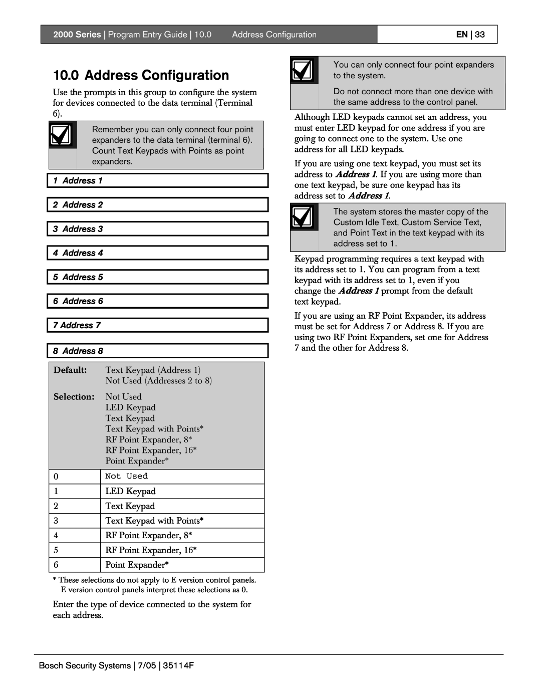
Address Configuration
10.0 Address Configuration
1 Address 2 Address 3 Address 4 Address 5 Address
6 Address 7 Address 8 Address
2000 Series Program Entry Guide
Address Configuration
EN
Bosch Security Systems 7/05 35114F
Point Codes
11.0 Point Codes
1 Point
2 Point
5 Point
4 Point
6 Point
7 to 24 Points 7 to
Refer to Section 11.3 Digit 3, Point Options
11.1Digit 1, Point Type
2000 Series Program Entry Guide
Point Codes
2000 Series Program Entry Guide
11.3 Digit 3, Point Options
Point Codes
EN
2000 Series Program Entry Guide
Point Codes
EN
2000 Series Program Entry Guide
Point Codes
EN
2000 Series | Program Entry Guide |
Point Codes
EN
2000 Series Program Entry Guide
the Extended Delay feature
Point Codes
EN
11.2Digit 2, Alarm Responses
2000 Series Program Entry Guide
Point Codes
2000 Series Program Entry Guide
11.3Digit 3, Point Options
Point Codes
EN
2000 Series Program Entry Guide
11.4Digit 4, Device Address
Point Codes
EN
11.5Digit 5, Sensor Loop
2000 Series Program Entry Guide
Point Codes
Point Codes
2000 Series Program Entry Guide
EN
Table 9 Digit Selection Summary
11.6 Recommended Point Codes
2000 Series Program Entry Guide
Point Codes
2000 Series Program Entry Guide
Point Codes
Table 16 Panic Device swinger bypass
Point Codes
2000 Series Program Entry Guide
EN
Bosch Security Systems 7/05 35114F
Point Text
12.0 Point Text
1 to 24 Point Text
2000 Series Program Entry Guide
Point Text
2000 Series Program Entry Guide
EN
Bosch Security Systems 7/05 35114F
13.1Relay Function Logic
13.0 Relays
13.2Relay Functions
Relays
2000 Series Program Entry Guide
the Parameter prompt
Relays
EN
2000 Series Program Entry Guide
Relays
EN
13.3Relay Parameters, for Keypad Programming Only
2000 Series Program Entry Guide
Relays
14.0 User Test
2 User Tst, Battery
User Test
1 User Tst, Bell
User Test
2000 Series Program Entry Guide
EN
Bosch Security Systems 7/05 35114F
Passcodes
15.0 Passcodes
1 Instir Code
2 Passcode Length
Passcode-#
5 Change Passcode
the Passcode Type and to enter a unique
passcode for up to eight users
RF Parameters
16.0 RF Parameters
1 Supervision Interval
2000 Series Program Entry Guide
RF Parameters
2000 Series Program Entry Guide
EN
Bosch Security Systems 7/05 35114F
3 Disable System
1 Return to Default
17.0 Program Lock
Program Lock
Program Lock
2000 Series Program Entry Guide
EN
Bosch Security Systems 7/05 35114F
18.1Getting Started
18.0Keypad Programming
18.2View Mode
Keypad Programming
18.4Scroll Lists
18.3Modify Mode
18.5Yes and No Entries
18.4 Scroll Lists
18.6An Example, Entering Custom Text
2000 Series Program Entry Guide
Keypad Programming
18.7Keypad Programming Tips
2000 Series Program Entry Guide
Keypad Programming
2000 Series Program Entry Guide Index
Index
2000 Series Program Entry Guide Index
2000 Series Program Entry Guide Index
Bosch Security Systems 130 Perinton Parkway
Fairport, NY Customer Service
Technical Support
2005 Bosch Security Systems 35114F