Network Tools
Example:
LINK TRAP STATUS:
Port 1 | is ENABLED | Port 2 | is DISABLED |
Port 3 | is ENABLED | Port 4 | is ENABLED |
Link traps have been DISABLED on port 2
Link traps have been DISABLED on all ports
Link traps are ENABLED on port 3
atm_stp_state:
NOTE |
The atm_stp_state command is only available if an
Syntax: | atm_stp_state [STATE] | |
Description: | The atm_stp_state command allows the user to | |
| enable, disable, or check the status of the | |
| Spanning Tree Algorithm on all ATM | |
| interfaces. The user must specify the STATE | |
| option as enable, disable, or status. The STATE | |
| field is mandatory. | |
Options: | enable, disable, status | |
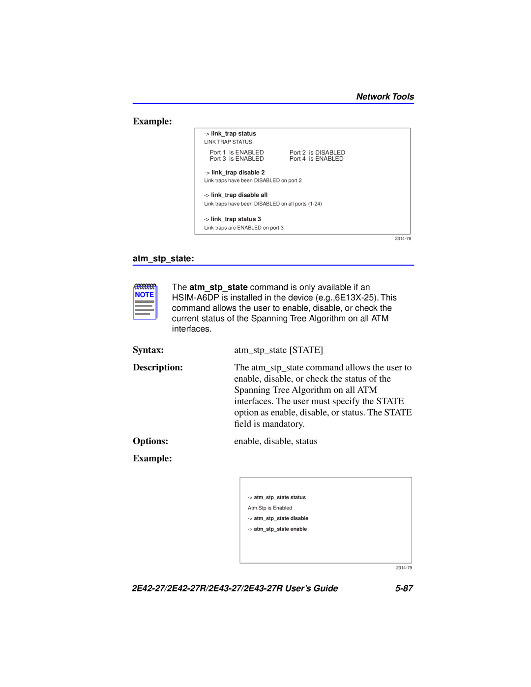
Example: |
|
|
|
|
|
|
| |
|
| Atm Stp is Enabled |
|
| |
|
| |
|
|
|
| ||
|