Connecting to the Network
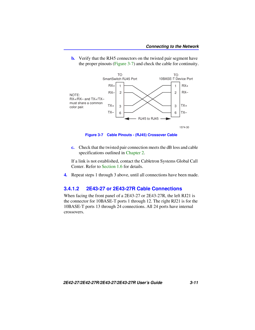
b.Verify that the RJ45 connectors on the twisted pair segment have the proper pinouts (Figure
|
| TO | |||
| SmartSwitch RJ45 Port | ||||
| RX+ |
|
|
|
|
| 1 |
|
|
| |
NOTE: | RX– | 2 |
|
|
|
|
|
|
|
| |
RX+/RX– and TX+/TX– |
|
|
|
| |
must share a common | TX+ | 3 |
|
|
|
color pair. |
|
|
| ||
| TX– | 6 |
|
|
|
|
|
|
|
|
|
|
|
|
|
|
|
TO
1 RX+
2 RX–
3 TX+
6 TX–
RJ45 to RJ45
Figure 3-7 Cable Pinouts - (RJ45) Crossover Cable
c.Check that the twisted pair connection meets the dB loss and cable specifications outlined in Chapter 2.
If a link is not established, contact the Cabletron Systems Global Call Center. Refer to Section 1.6 for details.
4.Repeat steps 1 through 3 above, until all connections have been made.
3.4.1.22E43-27 or 2E43-27R Cable Connections
When facing the front panel of a
|